
1.1产品规格概览Product Specifications
| 产品名称Product Name | FLOW AIO45 |
|---|---|
| 主控 / 核心芯片MCU | AT32F435 |
| 输入电压Input Voltage | 3–6S LiPo |
| 安装孔位Mounting Holes | 25.5 × 25.5 mm (M2),可通过转接板兼容 30 × 30 mm (M3)25.5 × 25.5 mm (M2), compatible with 30 × 30 mm (M3) via adapter board |
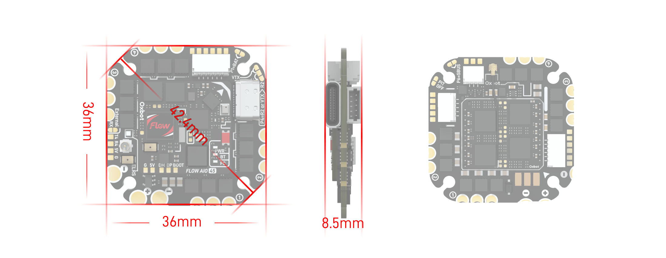
| 尺寸Dimensions | 36mm × 36mm × 8.5mm |
| 重量Weight | 12.6g |
| 持续电流Cont. Current | 45A / 180A |
| 峰值电流Peak Current | 50A / 200A (10S) |
| 5V BEC5V BEC | 最大电流 4A4A Max |
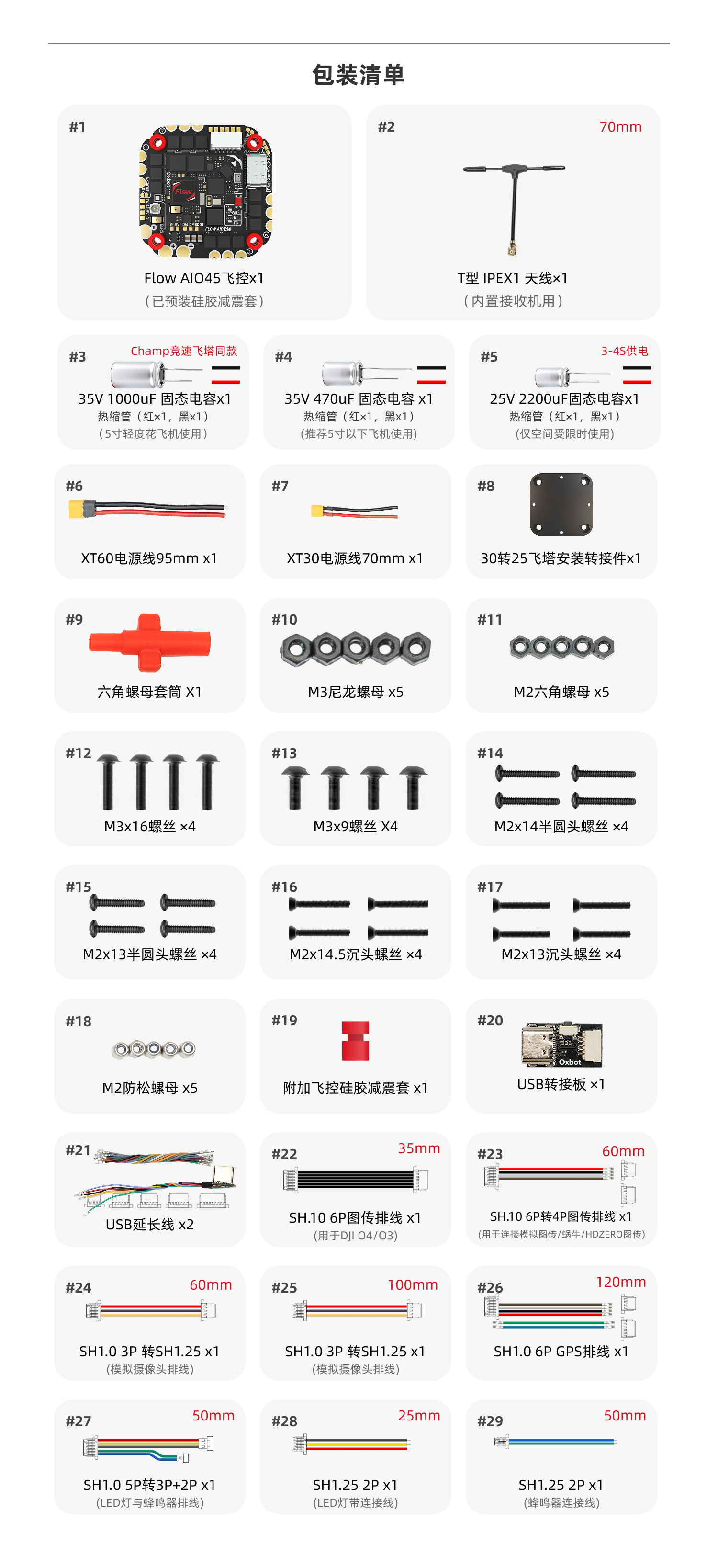
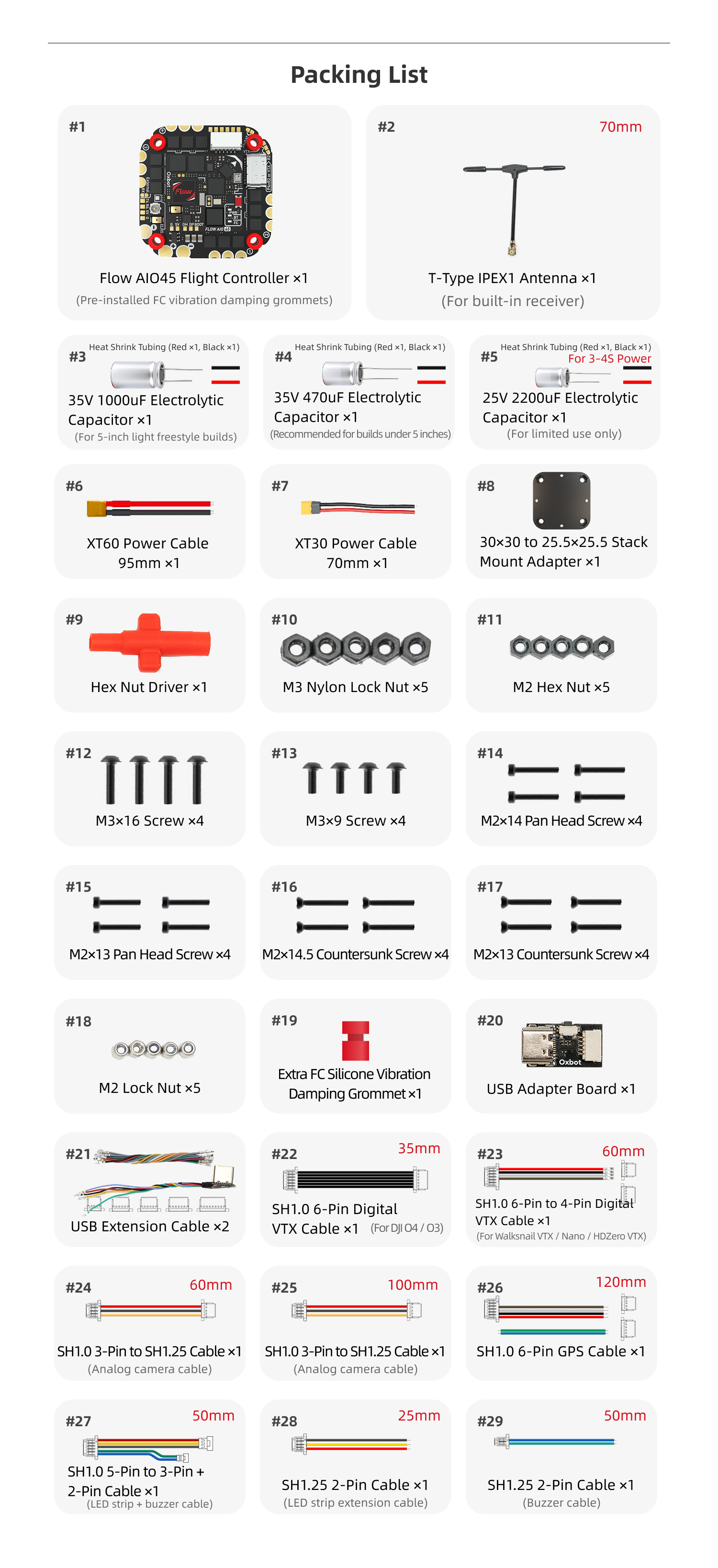
1.2包装配件概览Accessories Overview
| 编号 | 名称 | 备注 | 数量 |
|---|---|---|---|
| 1 | Flow AIO45飞控 | 已预装硅胶减震套 | 1 |
| 2 | T型 IPEX1 天线 | 内置接收机用,70mm | 1 |
| 3 | 35V 1000uF 固态电容 | 热缩管(红x1,黑x1);5寸轻度花飞机使用 | 1 |
| 4 | 35V 470uF 固态电容 | 热缩管(红x1,黑x1);推荐5寸以下飞机使用 | 1 |
| 5 | 25V 2200uF 固态电容 | 热缩管(红x1,黑x1);仅空间受限时使用 | 1 |
| 6 | XT60电源线 | 95mm | 1 |
| 7 | XT30电源线 | 70mm | 1 |
| 8 | 30转25飞塔安装转接件 | 1 | |
| 9 | 六角螺母套筒 | 1 | |
| 10 | M3尼龙螺母 | 5 | |
| 11 | M2六角螺母 | 5 | |
| 12 | M3x16螺丝 | 4 | |
| 13 | M3x9螺丝 | 4 | |
| 14 | M2x14半圆头螺丝 | 4 | |
| 15 | M2x13半圆头螺丝 | 4 | |
| 16 | M2x14.5沉头螺丝 | 4 | |
| 17 | M2x13沉头螺丝 | 4 | |
| 18 | M2防松螺母 | 5 | |
| 19 | 附加飞控硅胶减震套 | 1 | |
| 20 | USB转接板 | 1 | |
| 21 | USB延长线 | 2 | |
| 22 | SH1.0 6P图传排线 | 用于DJI O4/O3,35mm | 1 |
| 23 | SH1.0 6P转4P图传排线 | 用于连接模拟图传/蜗牛/HDZERO图传,60mm | 1 |
| 24 | SH1.0 3P转SH1.25 | 模拟摄像头排线,60mm | 1 |
| 25 | SH1.0 3P转SH1.25 | 模拟摄像头排线,100mm | 1 |
| 26 | SH1.0 6P GPS排线 | 120mm | 1 |
| 27 | SH1.25 2P | 蜂鸣器连接线,50mm | 1 |
| 28 | SH1.25 2P | LED灯带连接线,25mm | 1 |
| 29 | SH1.0 5P转3P+2P | LED灯与蜂鸣器排线,50mm | 1 |
| No. | Item | Notes | Qty |
|---|---|---|---|
| 1 | Flow AIO45 Flight Controller | Pre-installed FC vibration damping grommets | 1 |
| 2 | T-Type IPEX1 Antenna | For built-in receiver, 70mm | 1 |
| 3 | 35V 1000uF Electrolytic Capacitor | Heat Shrink Tubing (Red x1, Black x1); For 5-inch light freestyle builds | 1 |
| 4 | 35V 470uF Electrolytic Capacitor | Heat Shrink Tubing (Red x1, Black x1); Recommended for builds under 5 inches | 1 |
| 5 | 25V 2200uF Electrolytic Capacitor | Heat Shrink Tubing (Red x1, Black x1); For limited use only | 1 |
| 6 | XT60 Power Cable | 95mm | 1 |
| 7 | XT30 Power Cable | 70mm | 1 |
| 8 | 30×30 to 25.5×25.5 Stack Mount Adapter | 1 | |
| 9 | Hex Nut Driver | 1 | |
| 10 | M3 Nylon Lock Nut | 5 | |
| 11 | M2 Hex Nut | 5 | |
| 12 | M3×16 Screw | 4 | |
| 13 | M3×9 Screw | 4 | |
| 14 | M2×14 Pan Head Screw | 4 | |
| 15 | M2×13 Pan Head Screw | 4 | |
| 16 | M2×14.5 Countersunk Screw | 4 | |
| 17 | M2×13 Countersunk Screw | 4 | |
| 18 | M2 Lock Nut | 5 | |
| 19 | Extra FC Silicone Vibration Damping Grommet | 1 | |
| 20 | USB Adapter Board | 1 | |
| 21 | USB Extension Cable | 2 | |
| 22 | SH1.0 6-Pin Digital VTX Cable | For DJI O4 / O3, 35mm | 1 |
| 23 | SH1.0 6-Pin to 4-Pin Digital VTX Cable | For Walksnail VTX / Nano / HDZero VTX, 60mm | 1 |
| 24 | SH1.0 3-Pin to SH1.25 Cable | Analog camera cable, 60mm | 1 |
| 25 | SH1.0 3-Pin to SH1.25 Cable | Analog camera cable, 100mm | 1 |
| 26 | SH1.0 6-Pin GPS Cable | 120mm | 1 |
| 27 | SH1.25 2-Pin Cable | Buzzer cable, 50mm | 1 |
| 28 | SH1.25 2-Pin Cable | LED strip extension cable, 25mm | 1 |
| 29 | SH1.0 5-Pin to 3-Pin + 2-Pin Cable | LED strip + buzzer cable, 50mm | 1 |
1.3外观说明Appearance
适用于 2.5–5 寸机型(5 寸轻度花飞)。不推荐用于重度暴力花飞 5 寸,亦不推荐用于侧板全封闭、散热条件较差的机型。Suitable for 2.5-5 inch frames (light freestyle for 5"). Not recommended for heavy 5" freestyle or enclosed frames with poor cooling.
建议电机规格:不大于 2306 2000KV。Recommended: Not exceeding 2306 2000KV.
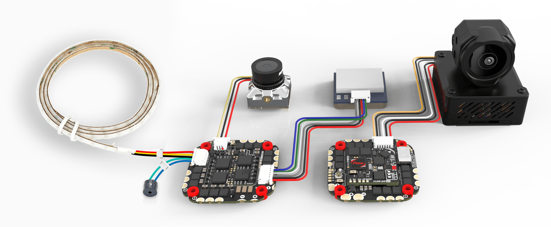
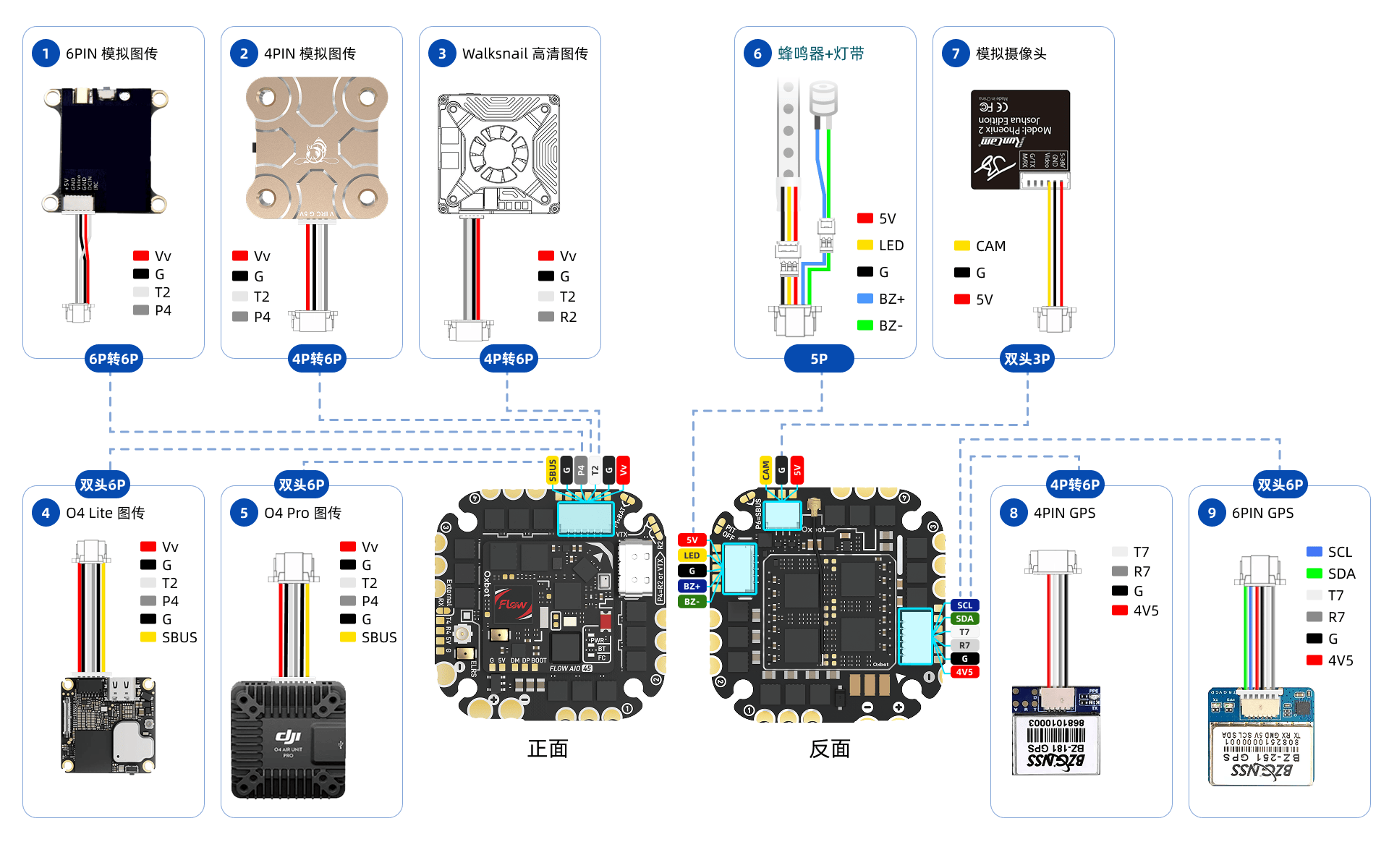
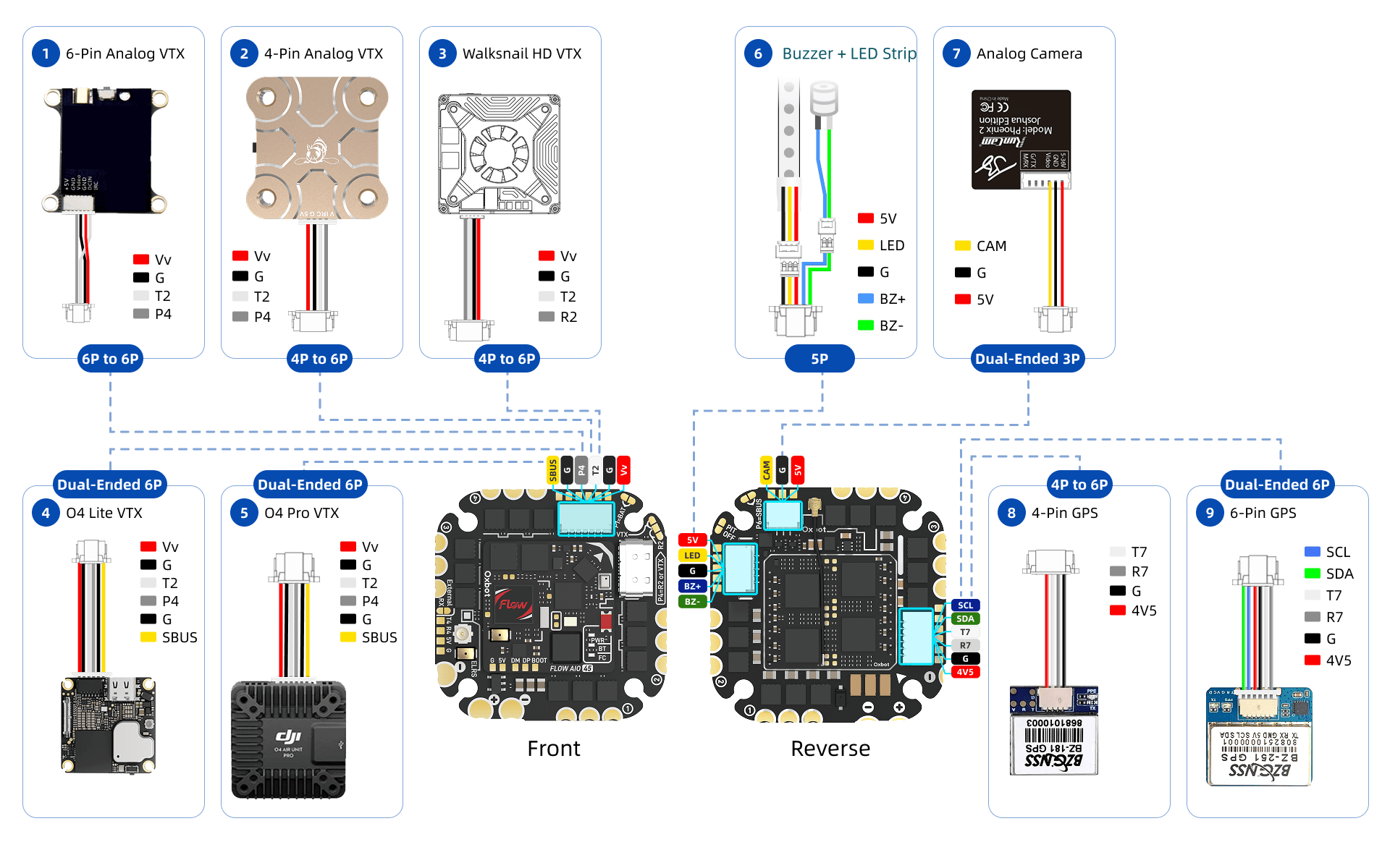
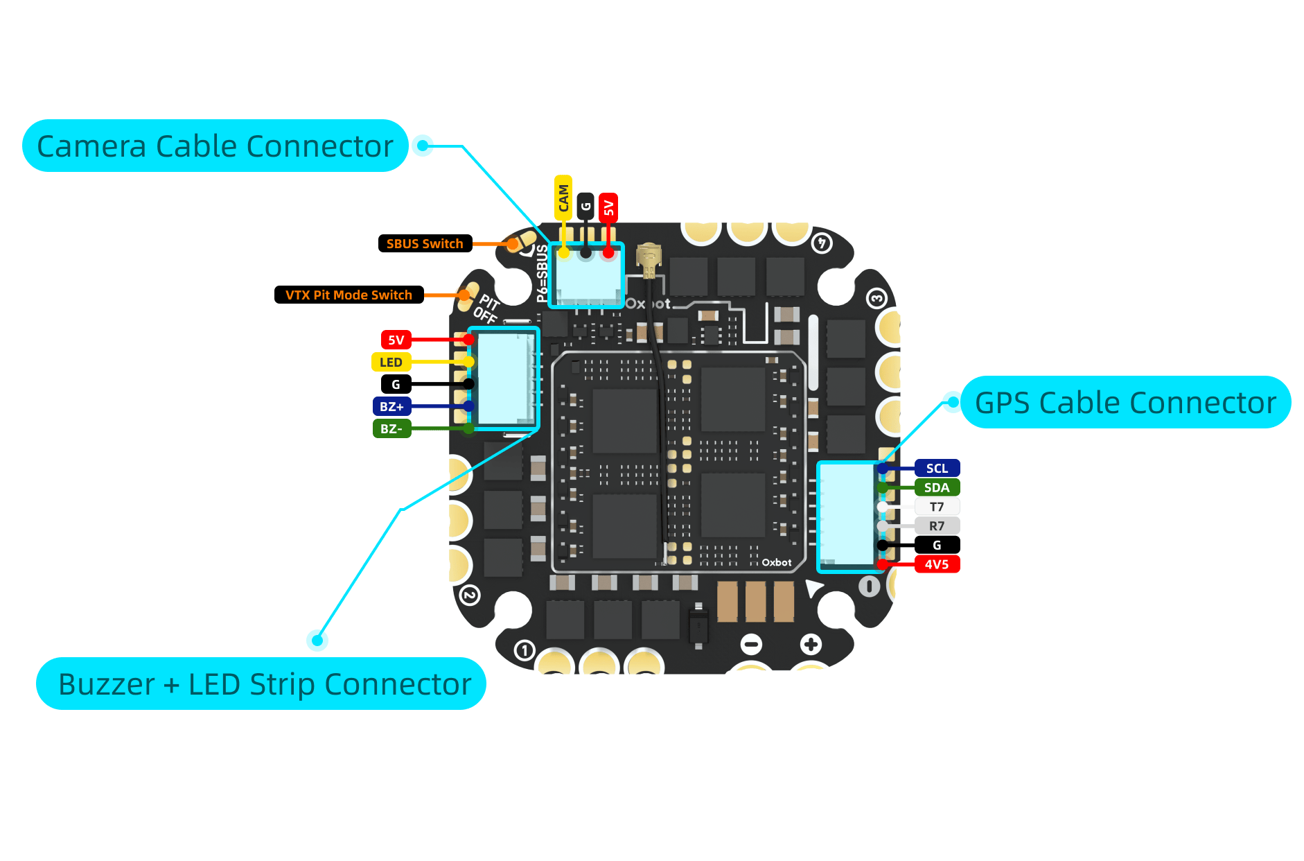
3.1外接设备连接概览Wiring Overview
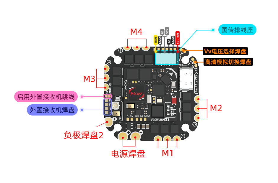
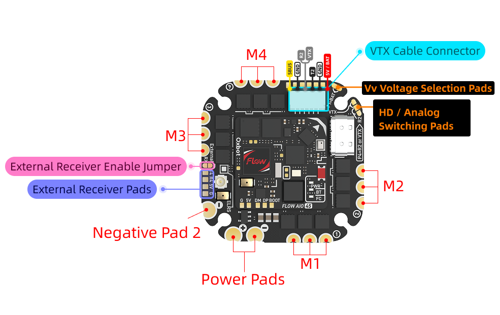
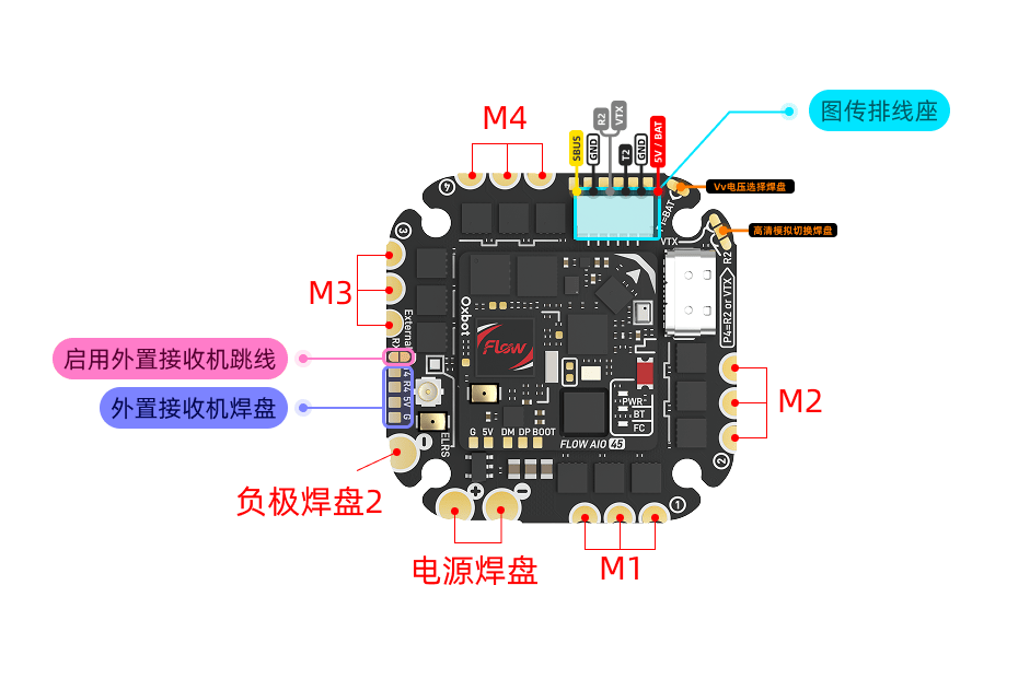
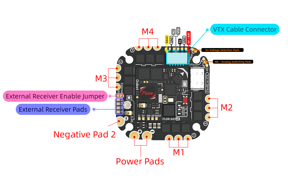
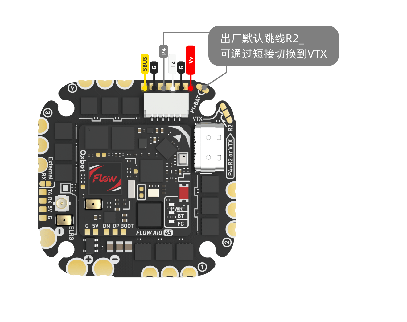
3.2焊盘定义Pad Definitions
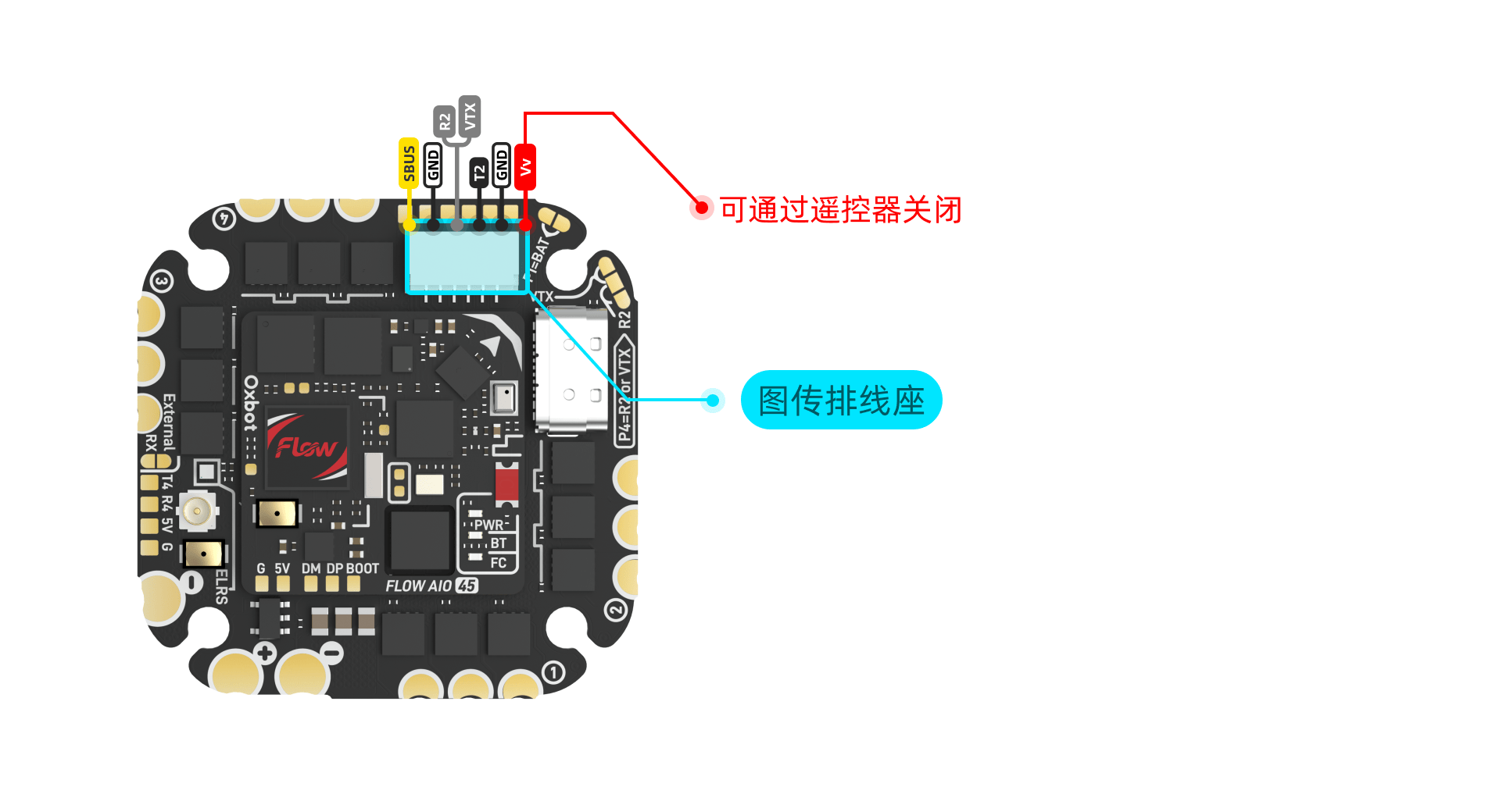
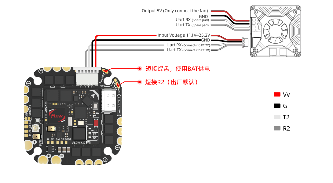
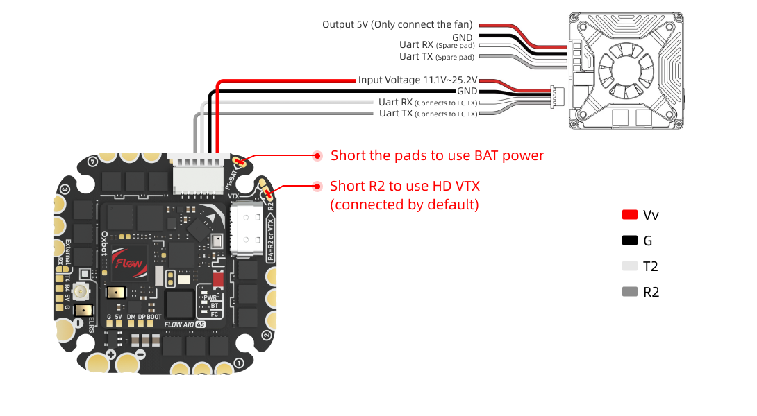
3.3高清图传连接HD VTX Connection
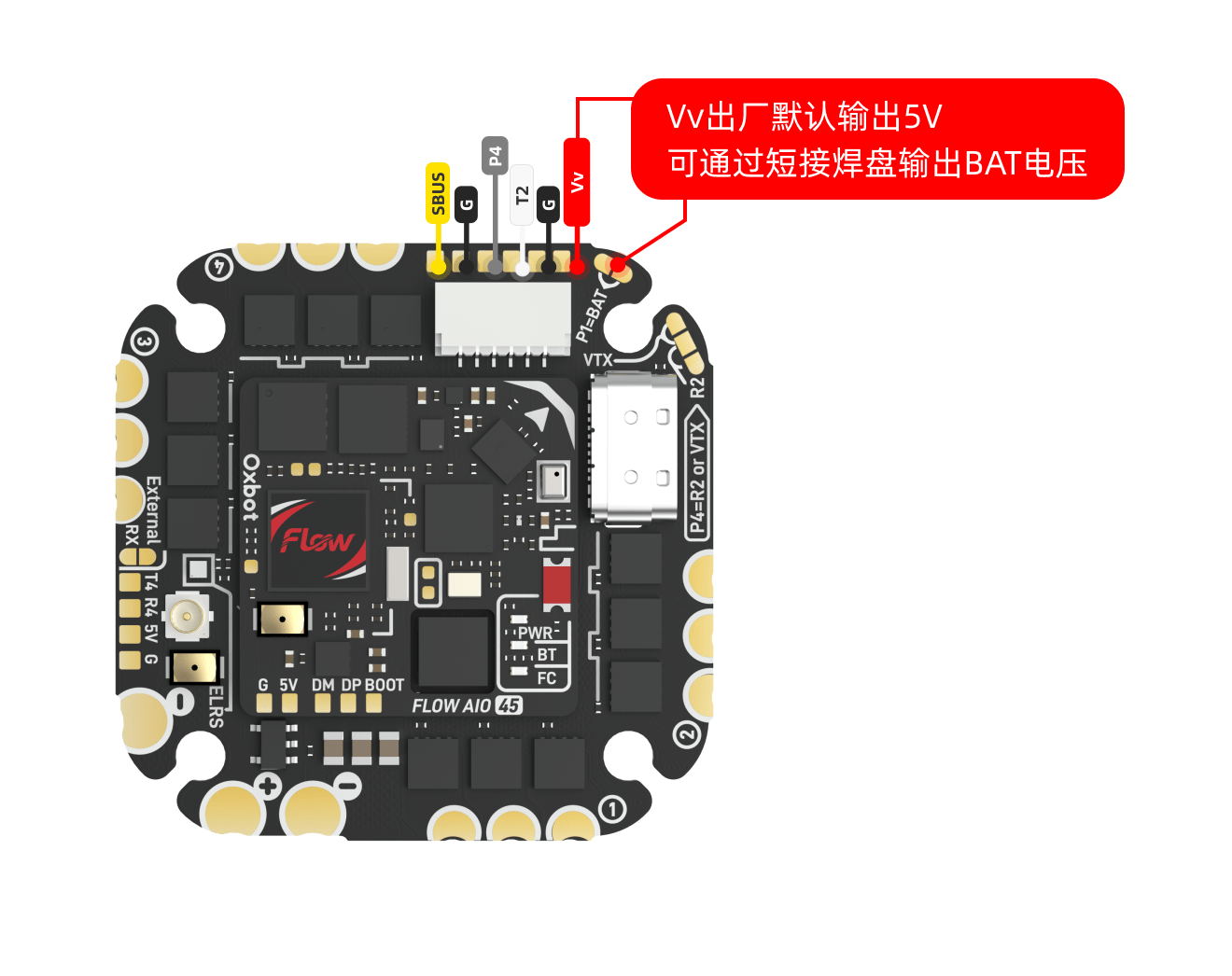
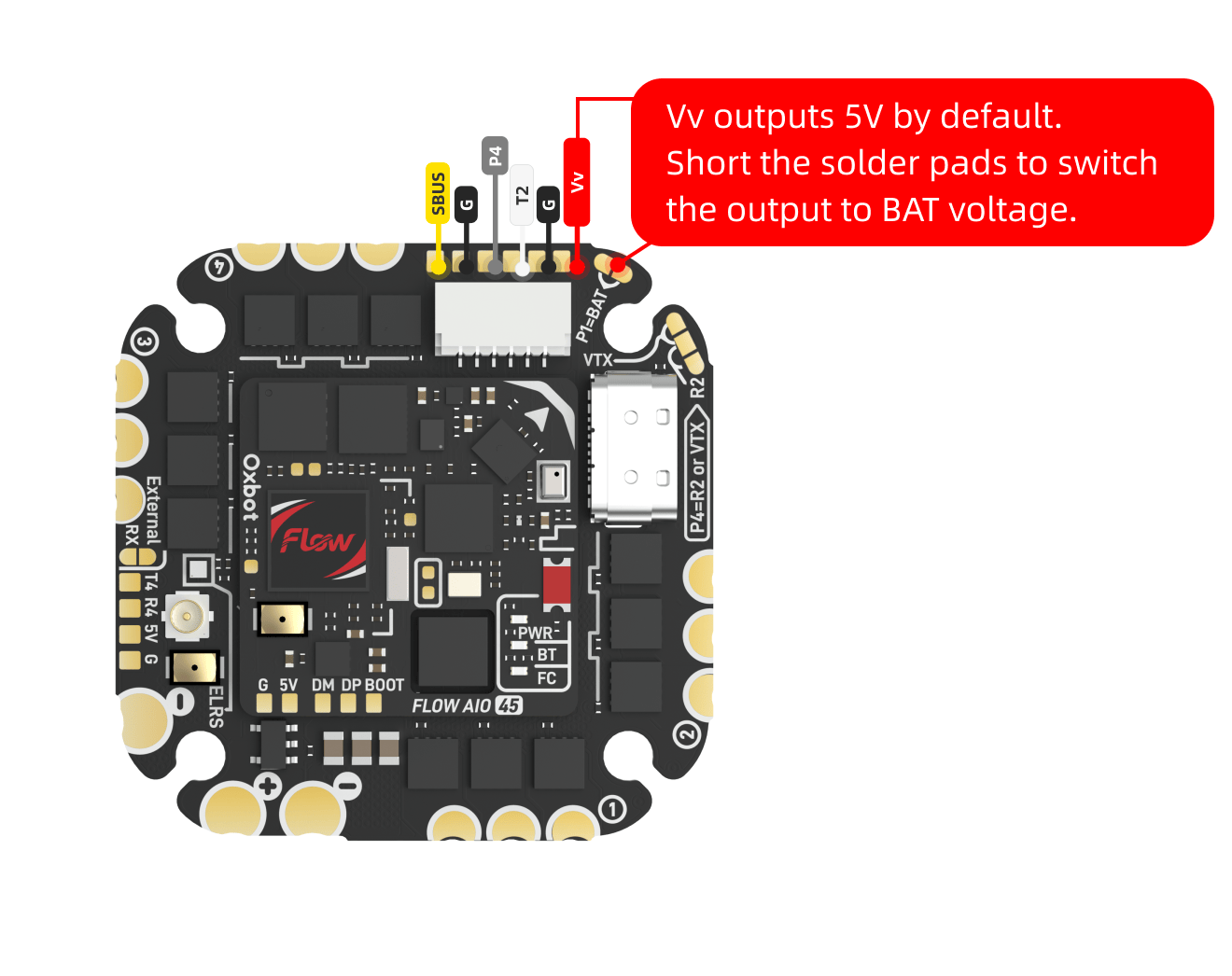
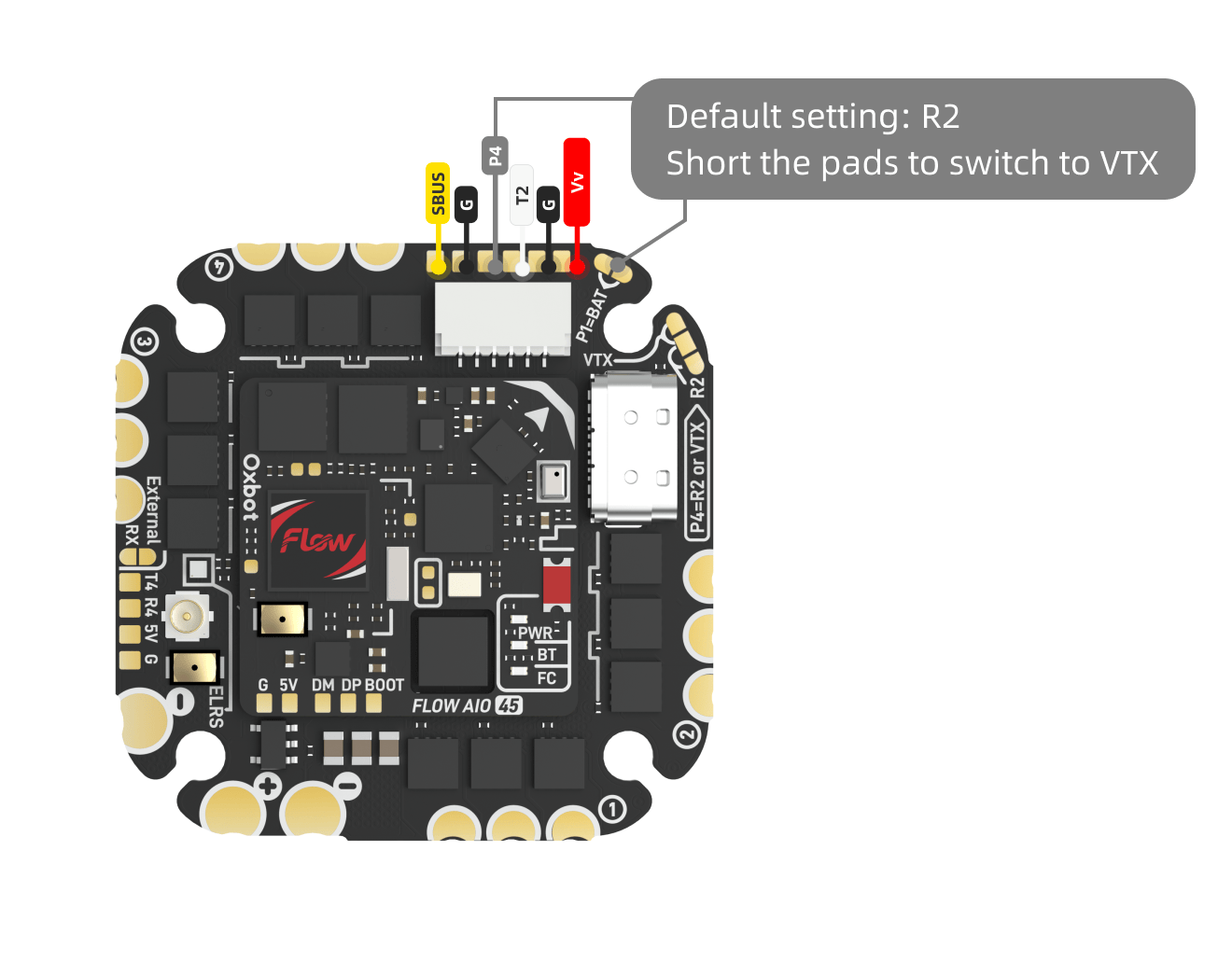
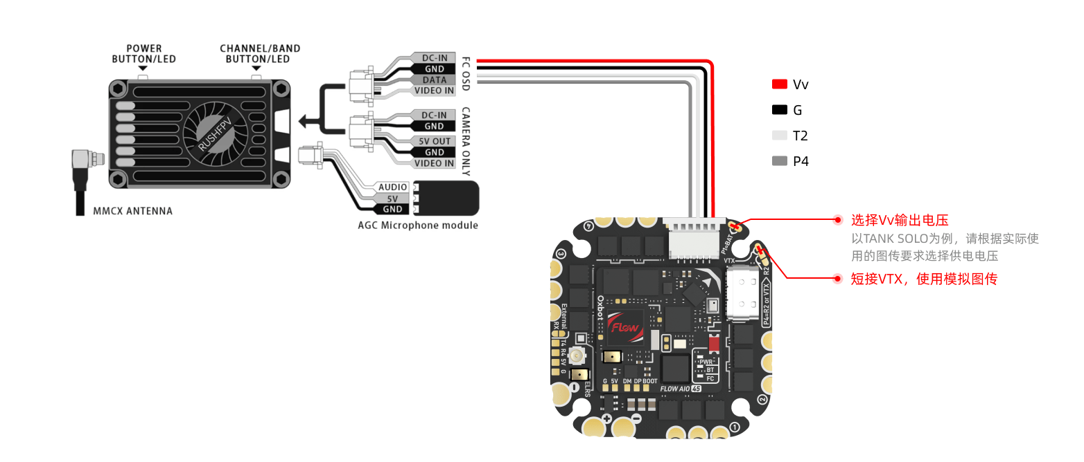
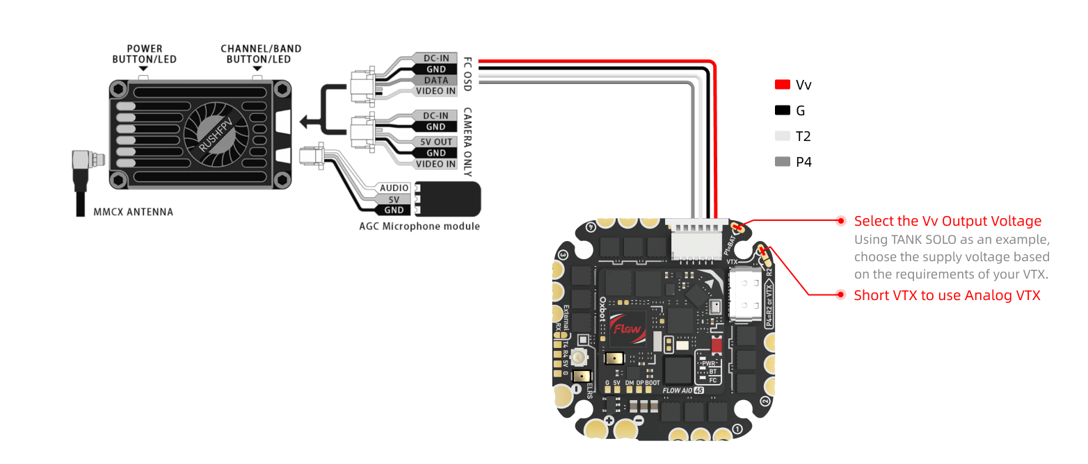
图传供电电压可通过跳线进行选择。出厂默认未短接跳线,图传端口输出 5V。手动将跳线切换至 BAT 后,图传端口输出电池电压。VTX power voltage is selectable via jumper. Factory default outputs 5V. Bridge to BAT for battery voltage output.
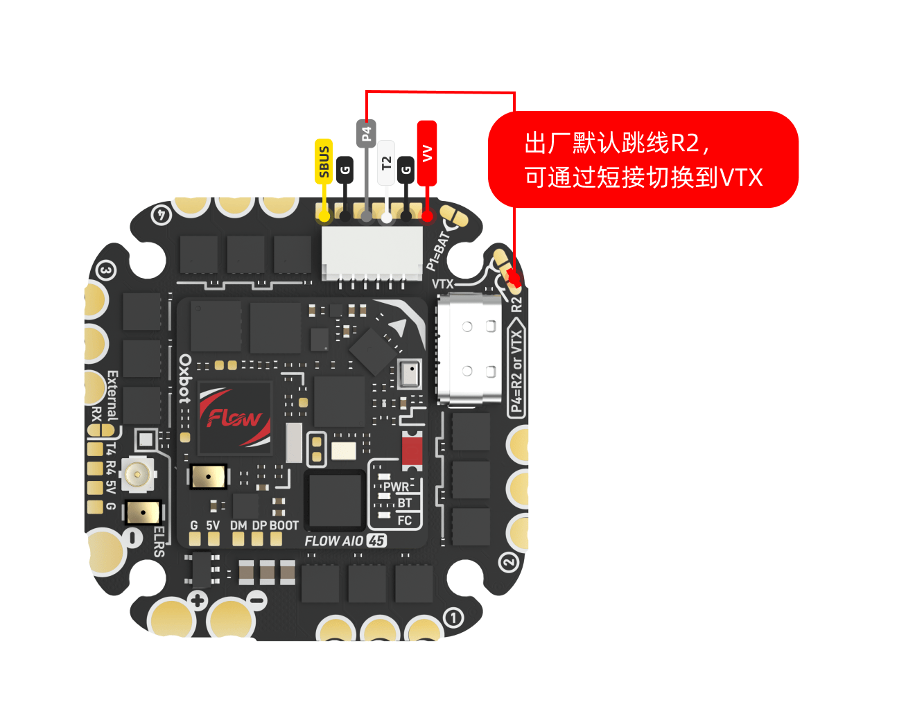
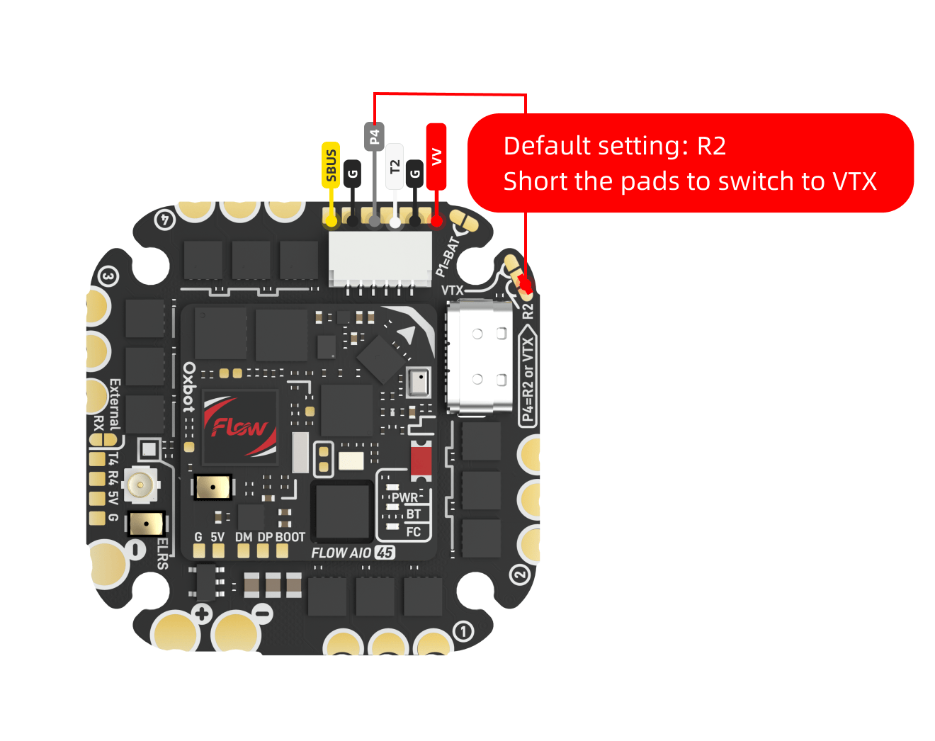
可通过图示焊盘切换 P4 接口的输出信号。使用前请确认当前焊盘状态与所接图传类型一致。Switch the P4 port output signal via the pads shown. Verify pad state matches your VTX type before use.
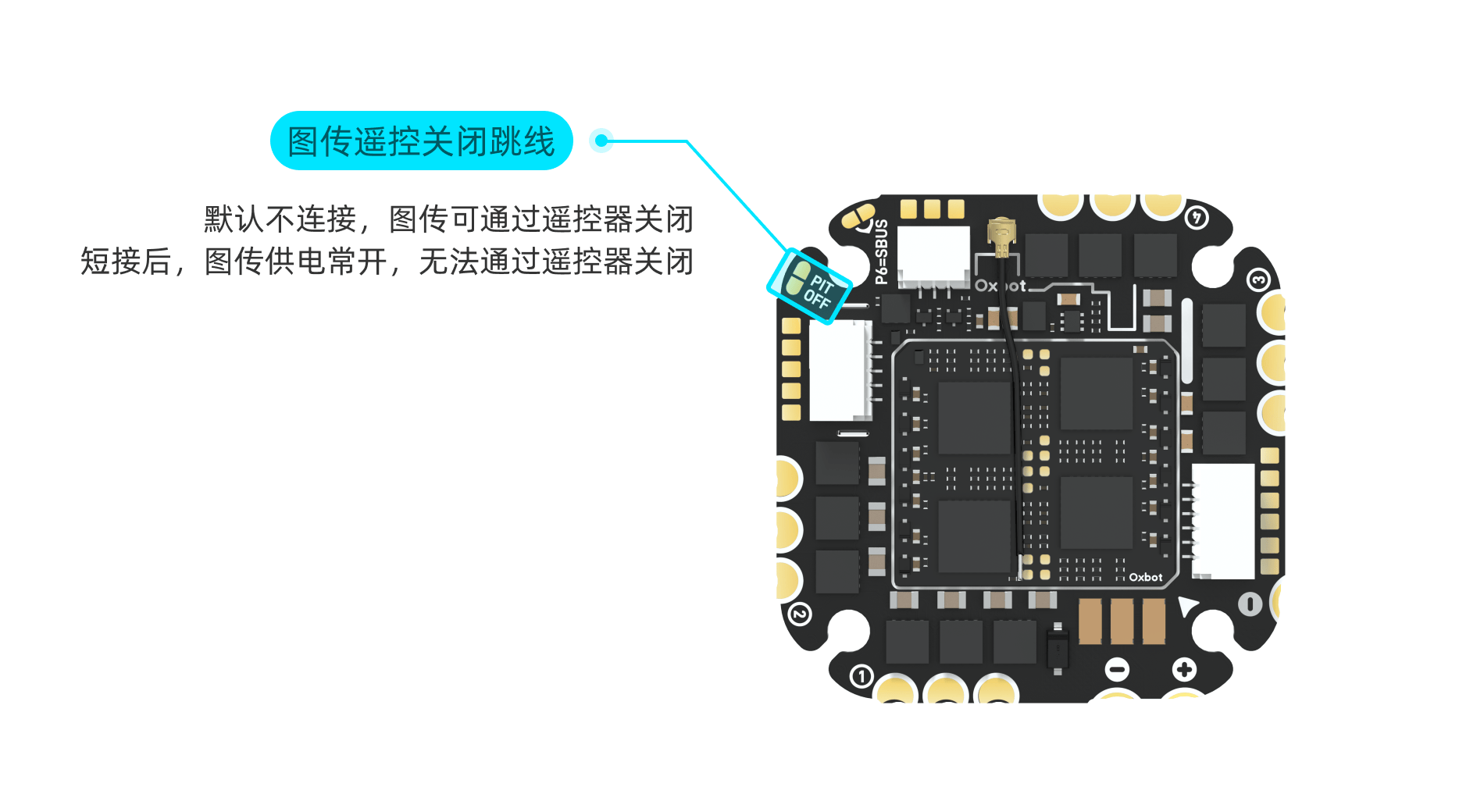
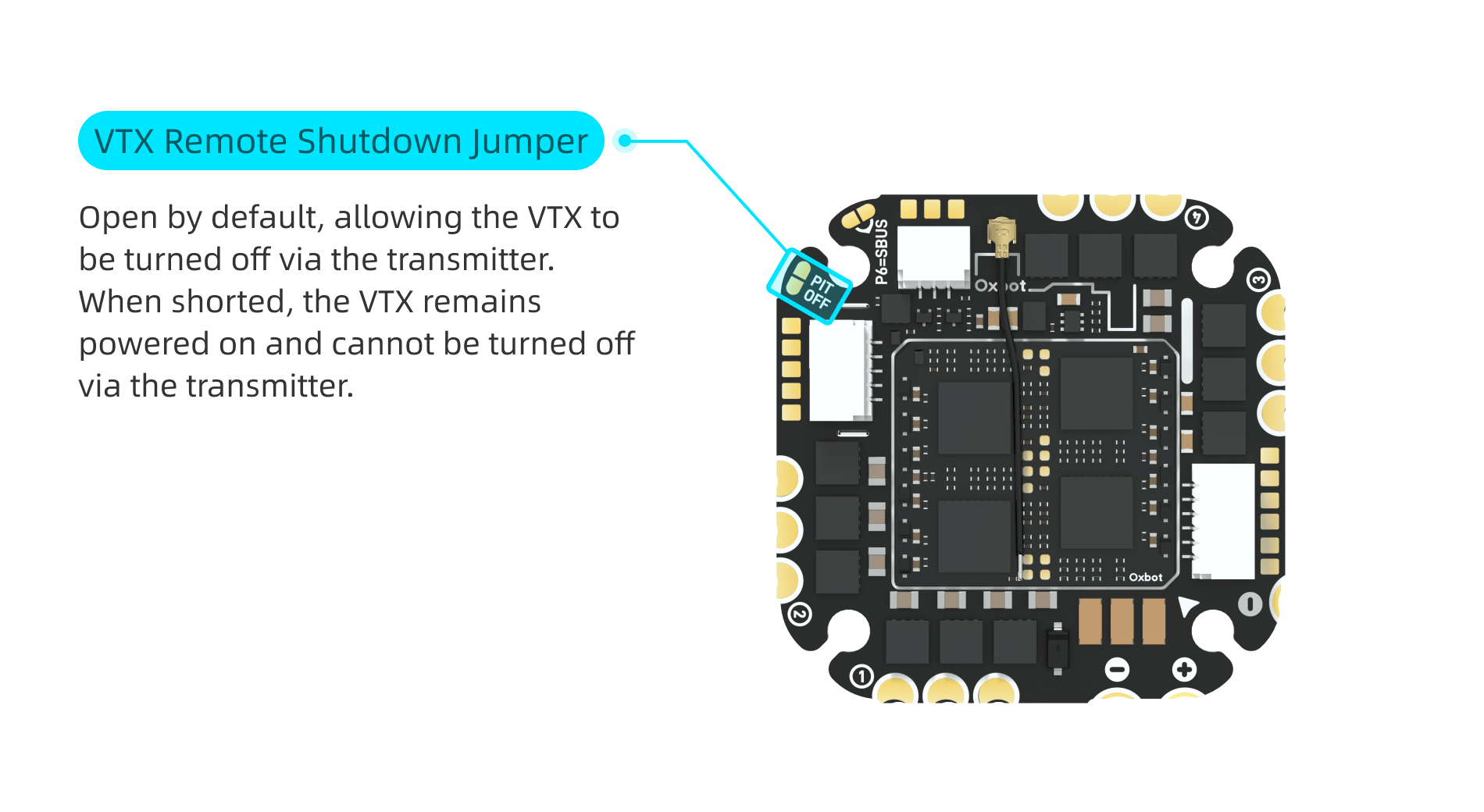
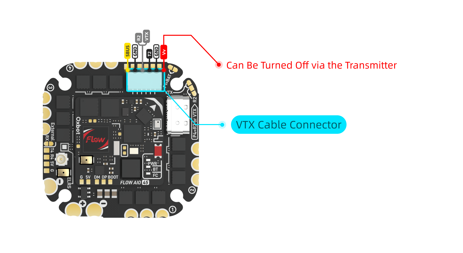
当飞控未连接 PIT OFF 时,可通过"VTX BEC OFF"模式控制图传端口供电。When PIT OFF is not connected, use "VTX BEC OFF" mode to control VTX port power.
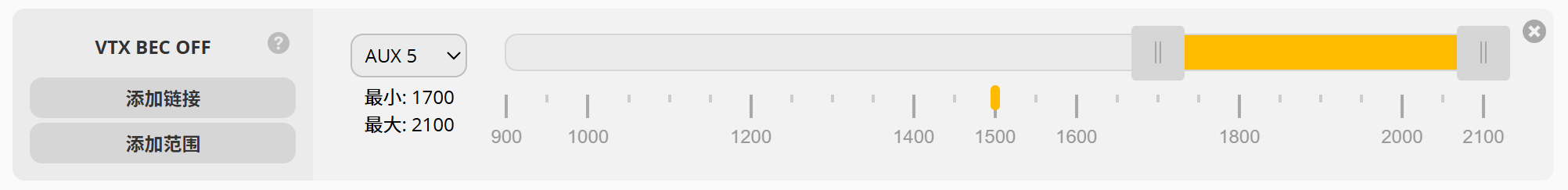
当 VTX BEC OFF 模式未激活时,图传正常供电。When VTX BEC OFF is inactive, VTX powers normally.
当 VTX BEC OFF 模式激活时,图传端口停止供电。When VTX BEC OFF is active, VTX port power is cut.
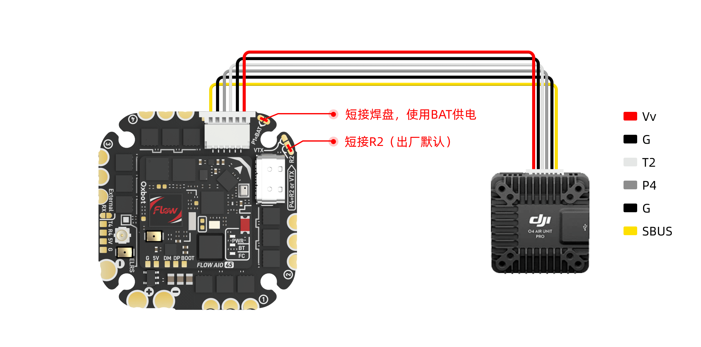
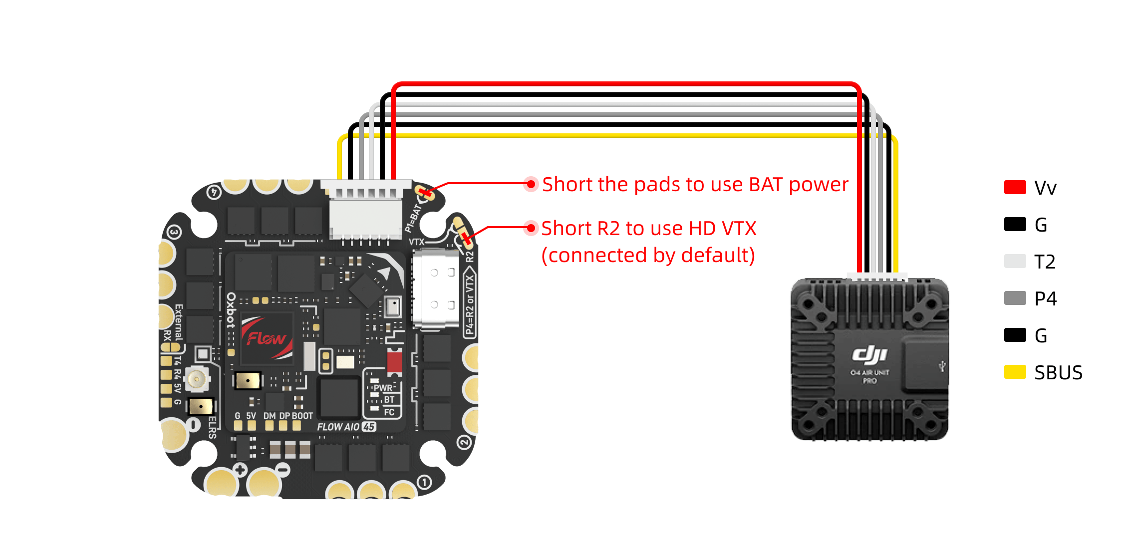
请按图示连接 O4 Pro 图传。可使用配件 #22 的图传 35mm 6PIN 线材(见 1.2 包装配件概览)进行连接,也可直接使用 DJI 原装线材。Connect O4 Pro as shown. Use accessory #22 (35mm 6PIN cable, see 1.2) or original DJI cable.
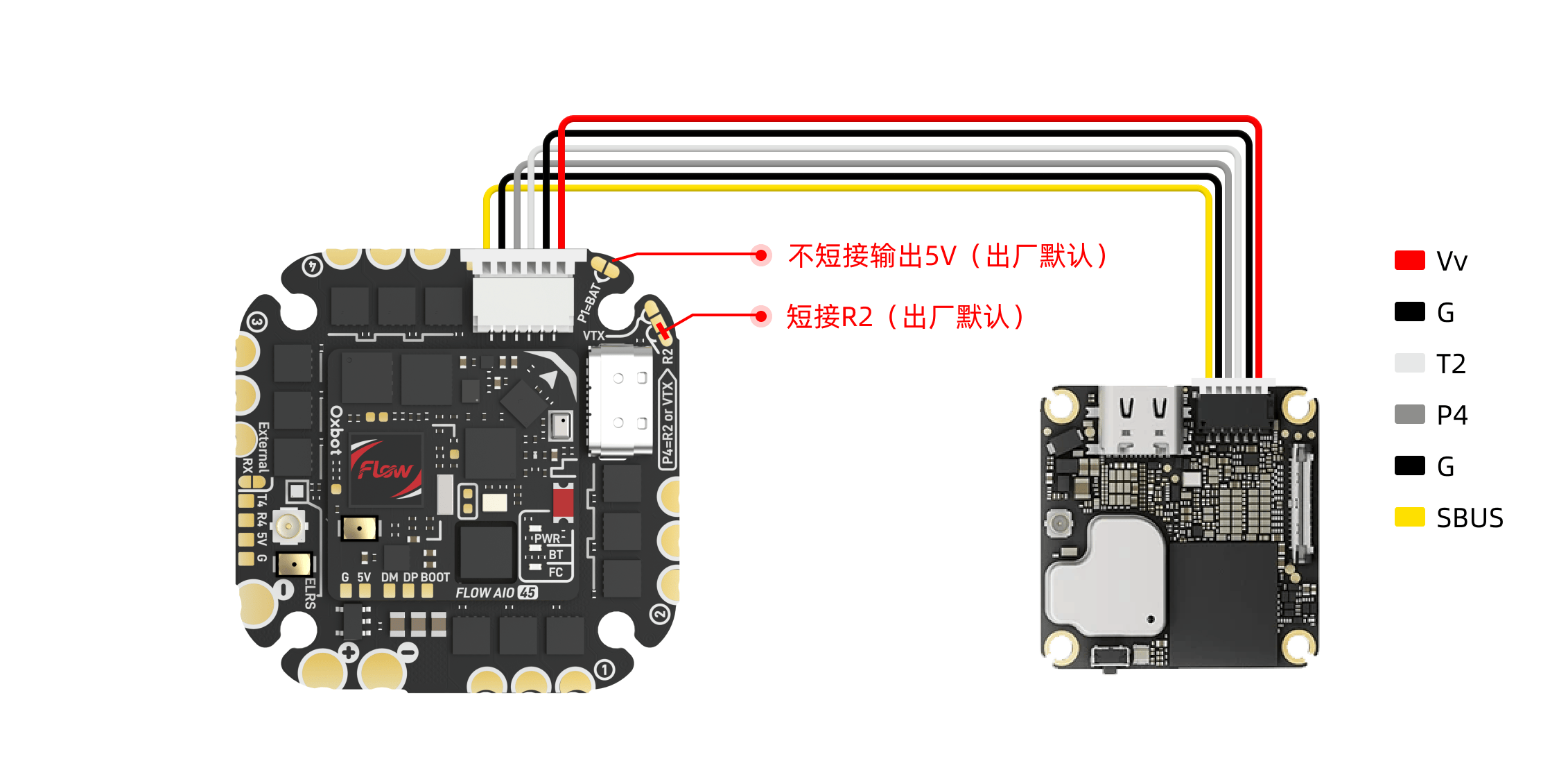
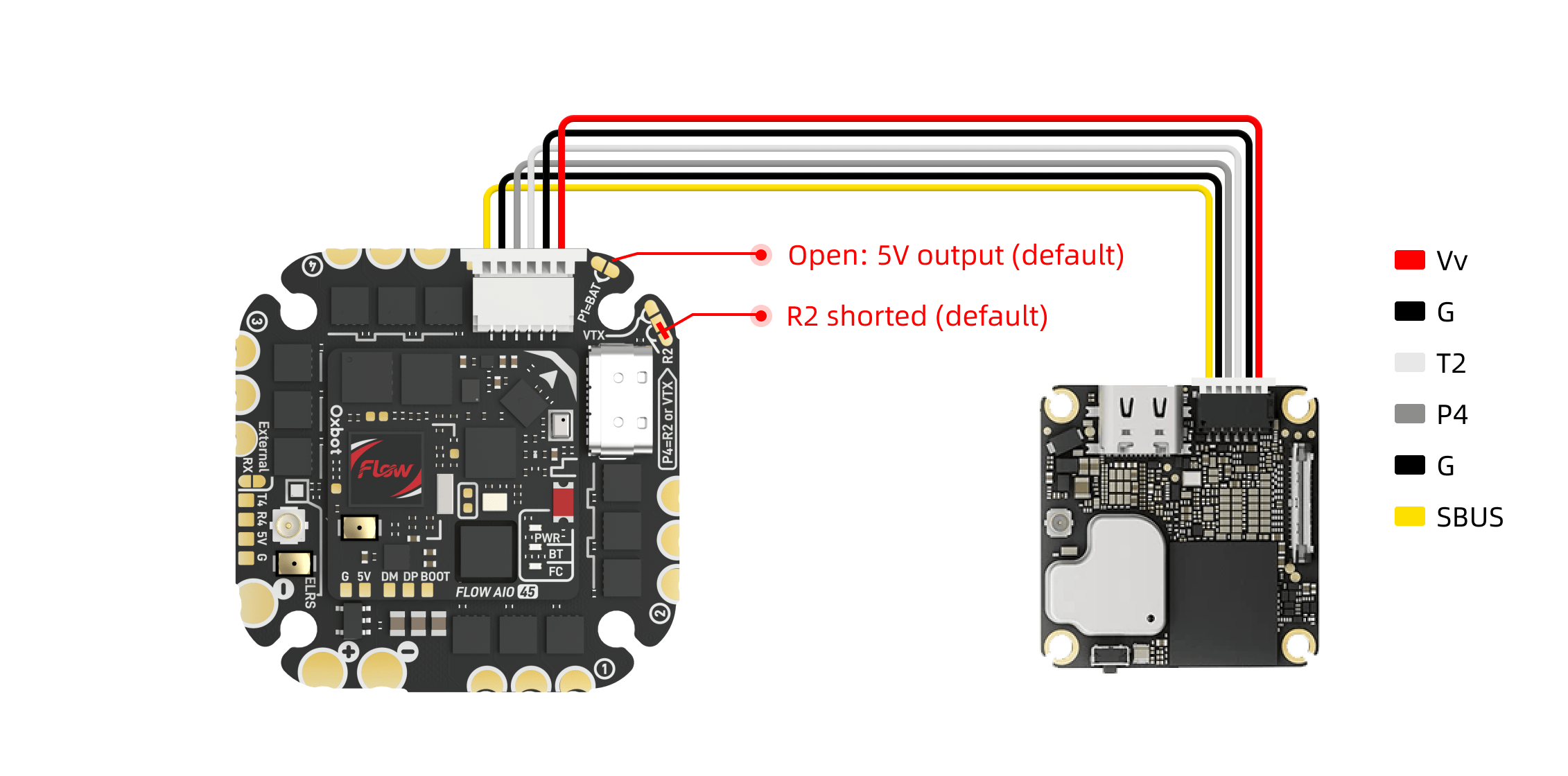
请按图示连接 O4 Lite 图传。可使用配件编号 #22 的图传 35mm 6PIN 线材或直接使用 DJI 原装线材。出厂默认已完成相关设置,无需额外配置。Connect O4 Lite as shown. Use accessory #22 (35mm 6PIN cable) or original DJI cable. Factory defaults are pre-configured.
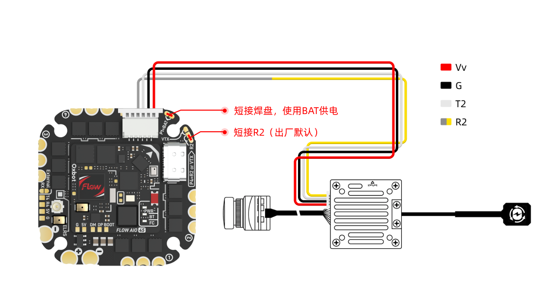
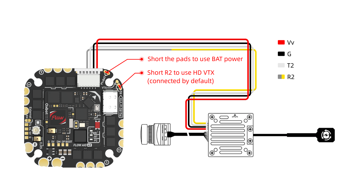
请按图示连接 Walksnail 高清图传。Connect Walksnail HD VTX as shown. 可使用配件编号 #23 的图传 60mm 4PIN 线材进行连接。该线材仅预装一端端子,另一端需根据图示线序,手动插入对应的 4PIN 胶壳后再连接图传。出厂默认已完成相关设置。Use accessory #23 (60mm 4PIN cable). One end is pre-terminated; manually insert the other end into the 4PIN shell per the pinout diagram. Factory defaults are pre-configured.
(1)接线图(以Freestyle V2 VTX 为例)(1) Wiring Diagram (Example: Freestyle V2 VTX)
HDZero Freestyle V2 需使用图传自带排线进行连接。由于 HDZero 默认线序与 DJI 不同,接线前请先按图示重新整理端子顺序,再插入接口。HDZero Freestyle V2 uses its own cable. Since HDZero pinout differs from DJI, re-arrange terminal order per the diagram before connecting.
(2)Betaflight 设置(2) Betaflight Settings
出厂默认已完成相关设置,无需额外配置。Factory defaults are pre-configured, no extra setup needed.
(3)注意事项(3) Notes
3.4模拟图传连接Analog VTX Connection
使用模拟图传时,需通过跳线将图传模式切换为模拟图传模式。When using analog VTX, switch mode to analog via the jumper pads.
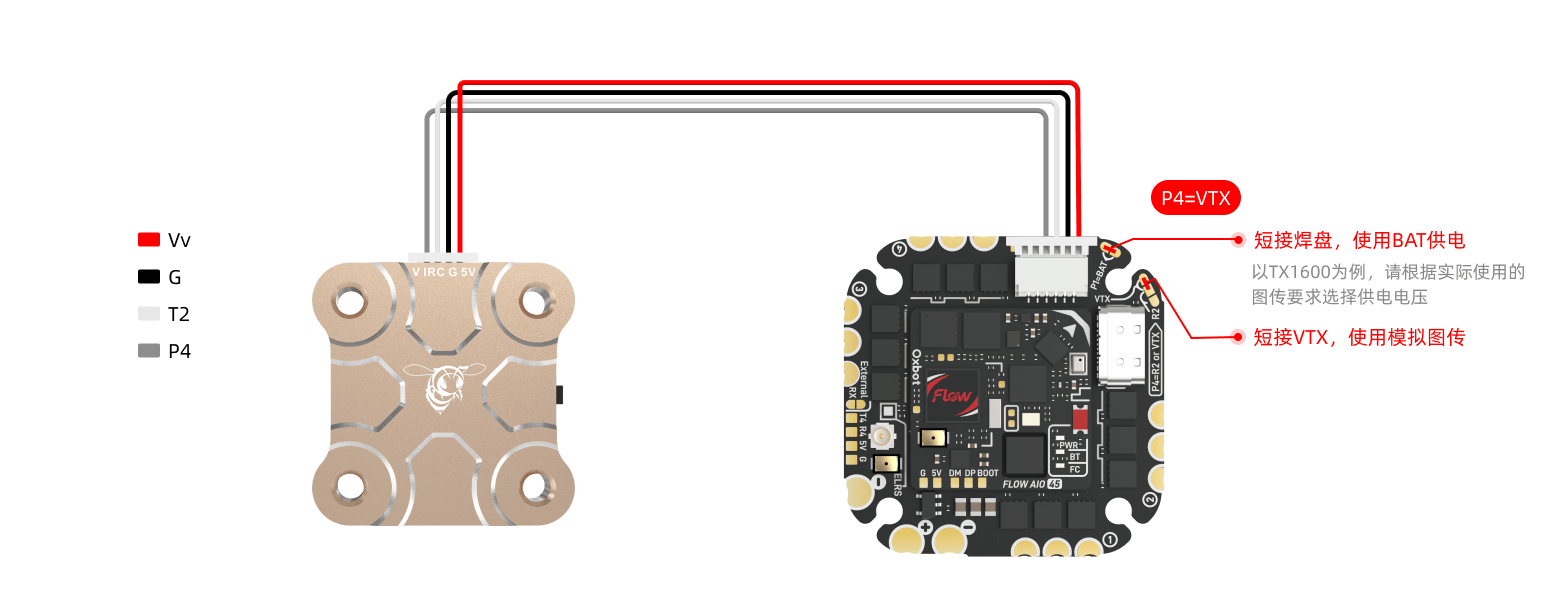
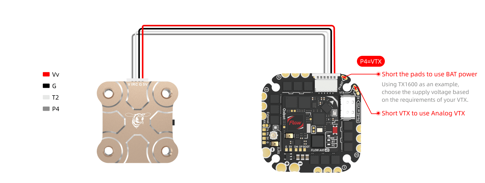
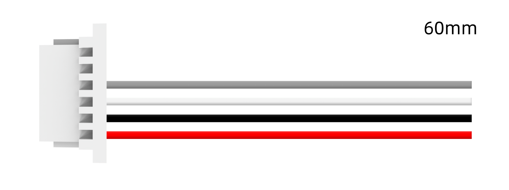
连接 4PIN 模拟图传时,可使用配件编号 #23 的图传 60mm 4PIN 线材。该线材仅预装一端端子,另一端需根据图示线序,手动插入配件编号 #11 的 4PIN 胶壳后再连接图传。For 4PIN analog VTX, use accessory #23 (60mm 4PIN cable). One end is pre-terminated; insert the other end into the accessory #11 4PIN shell per the pinout.
请在 Betaflight CLI 中输入以下命令并保存:Enter the following commands in Betaflight CLI and save:
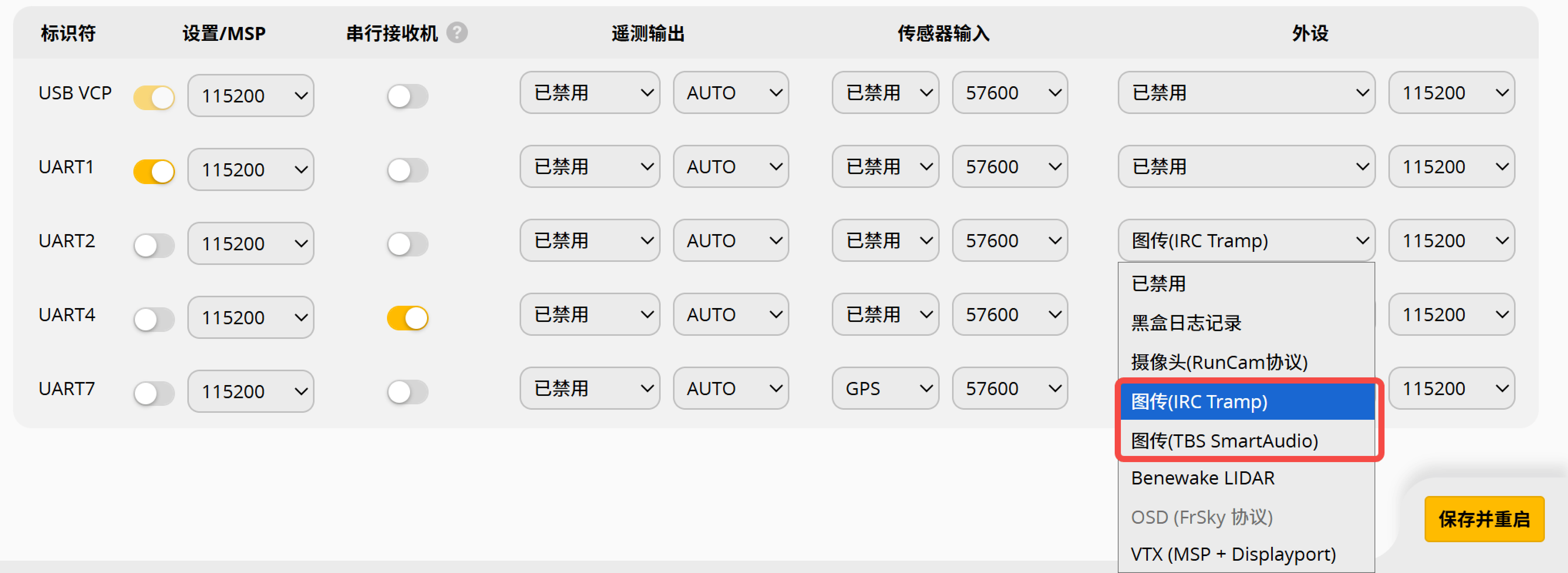
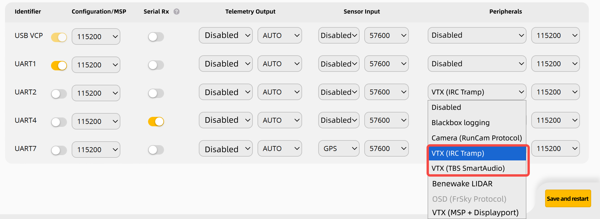
随后在 Ports 页签中,将 UART2 设置为对应的图传协议。若使用 IRC Tramp 或 TBS SmartAudio,请以图传说明书为准。Then in Ports tab, set UART2 to the appropriate VTX protocol. For IRC Tramp or TBS SmartAudio, refer to VTX documentation.
连接非 4PIN 模拟图传时,请根据图示线序,手动插入配件编号 #5 的 5PIN 胶壳或配件编号 #12 的 6PIN 胶壳后再连接设备。For non-4PIN analog VTX, manually insert into accessory #5 (5PIN shell) or #12 (6PIN shell) per the pinout.
Betaflight 设置同 3.4.2。Betaflight settings same as 3.4.2.
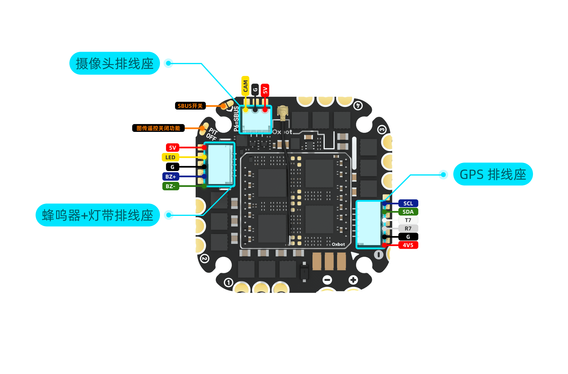
3.5模拟摄像头连接Analog Camera Connection
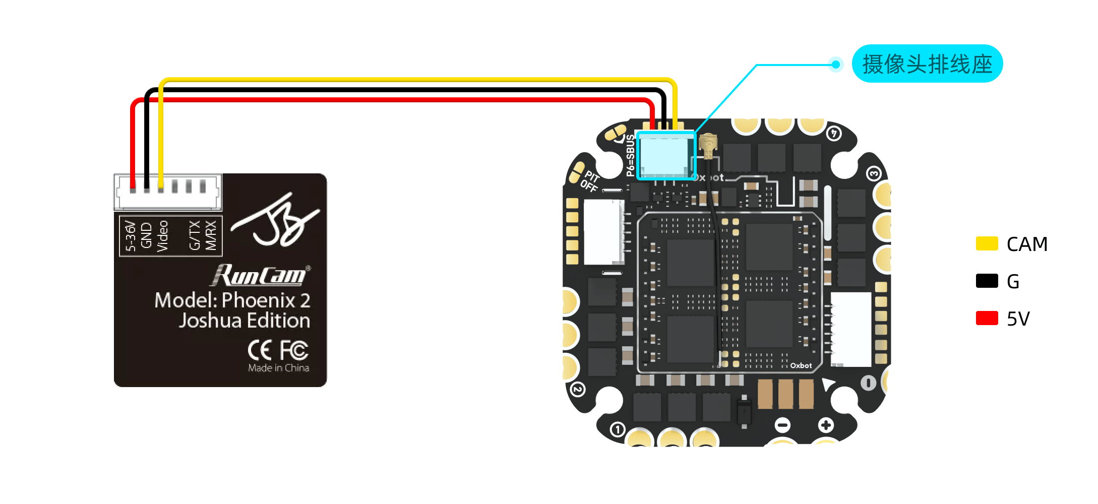
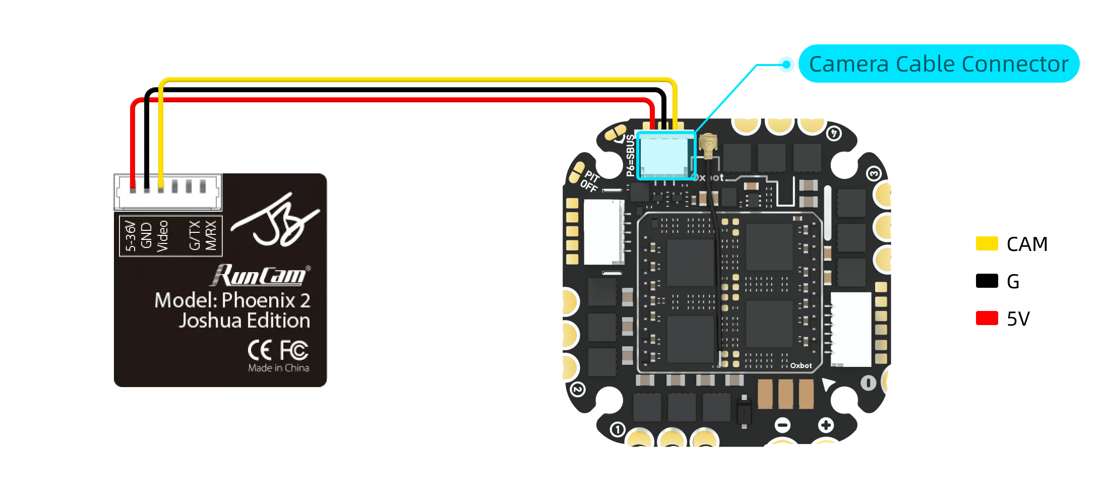
模拟摄像头可使用配件编号 #24 或 #25 的模拟摄像头排线进行连接。请根据机架内摄像头与飞控之间的实际距离选择合适长度的线材。接线前请先核对摄像头端与飞控端的线序。Connect analog camera using accessory #24 or #25 camera cables. Choose appropriate length based on frame layout. Verify pinout before connecting.
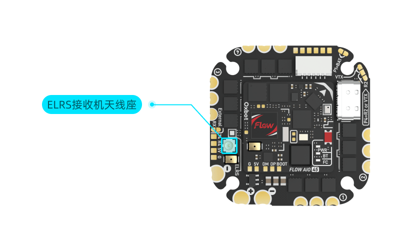
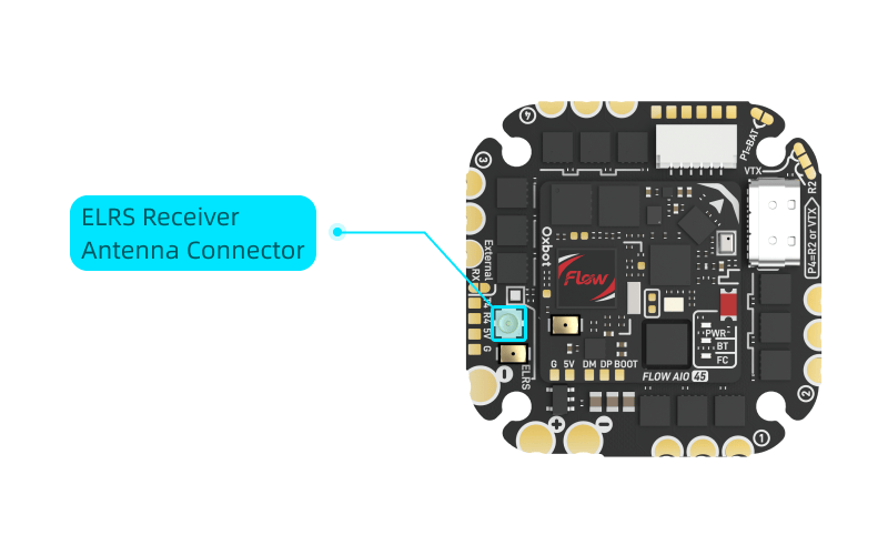
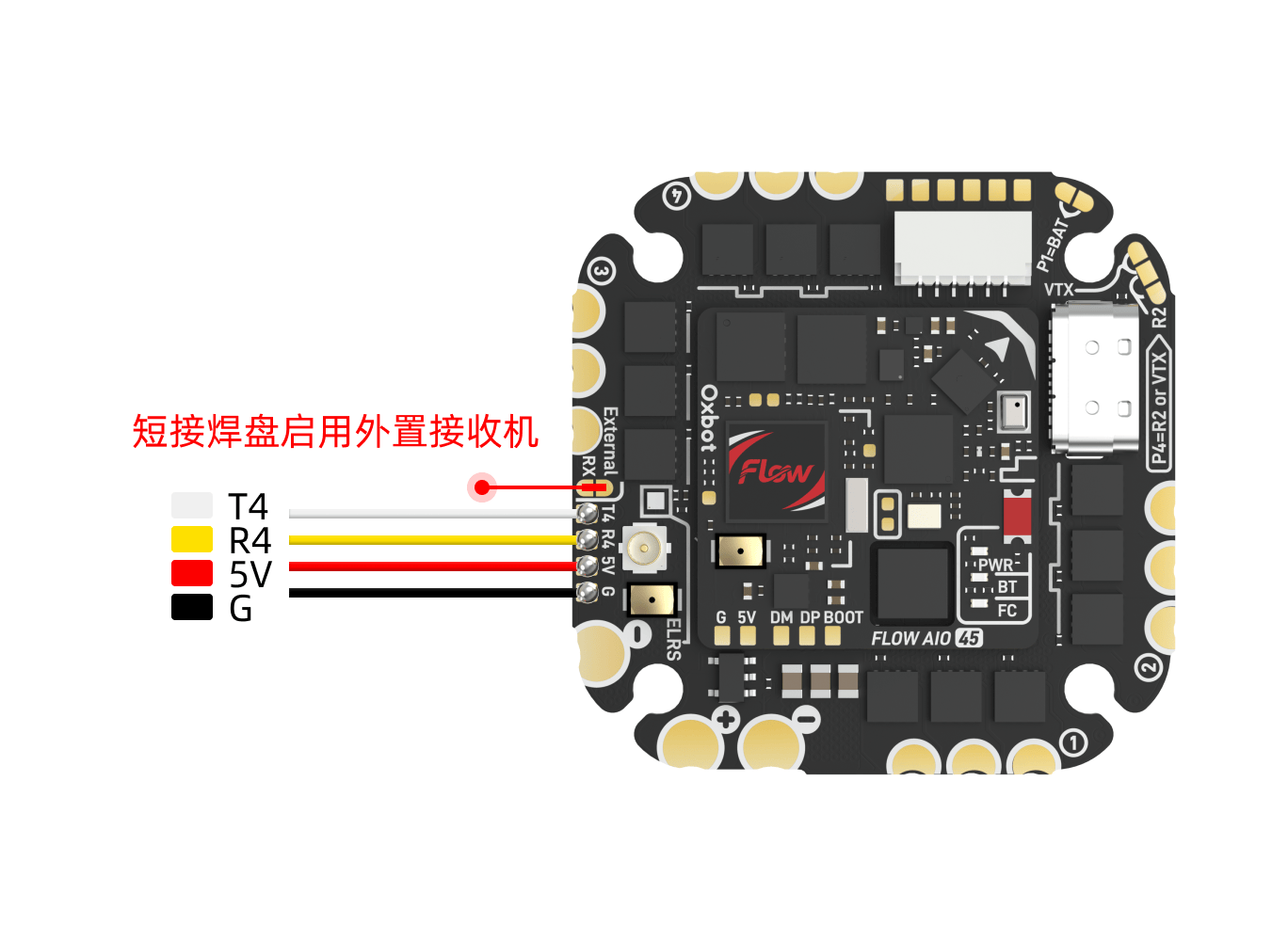
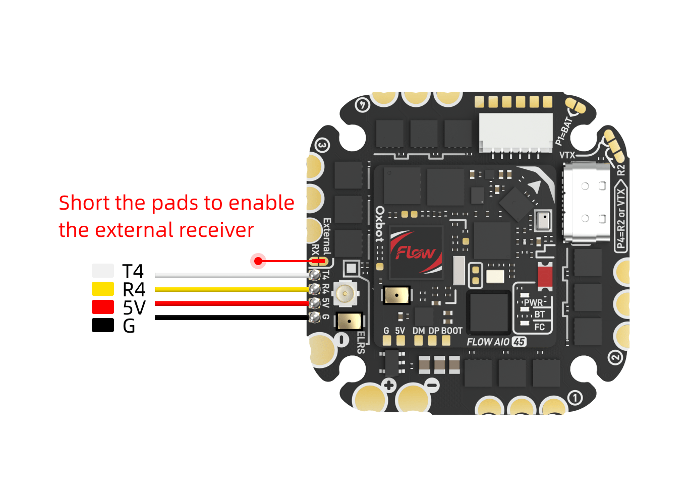
3.6接收机连接Receiver Connection
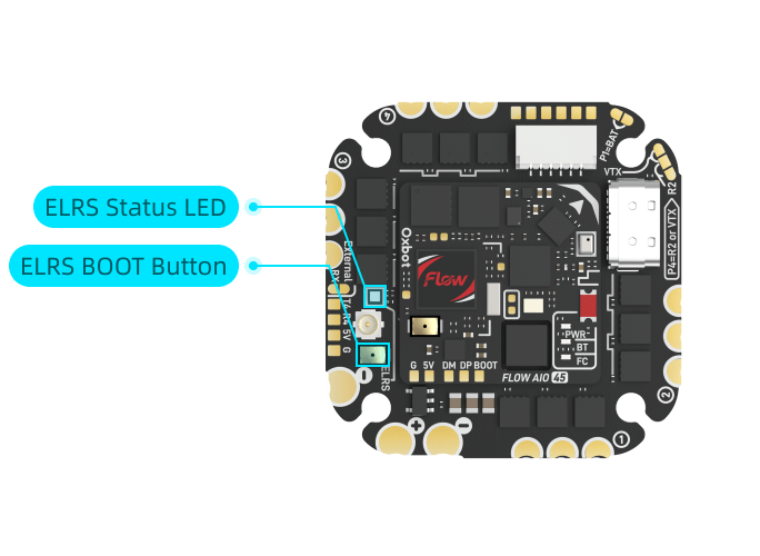
出厂默认已启用内置 ELRS 接收机,无需额外配置。使用前请先将配件编号 #2 的 ELRS 2.4G 接收机天线正确安装到飞控天线座上,再进行通电与对频操作。Built-in ELRS receiver is enabled by default. Install accessory #2 (ELRS 2.4G antenna) onto the FC antenna connector before powering on.
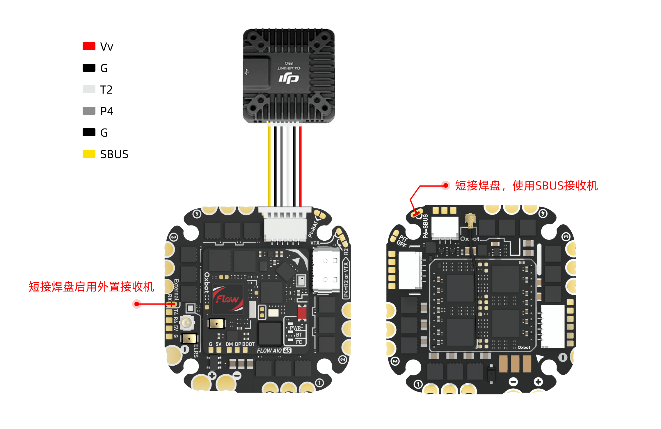
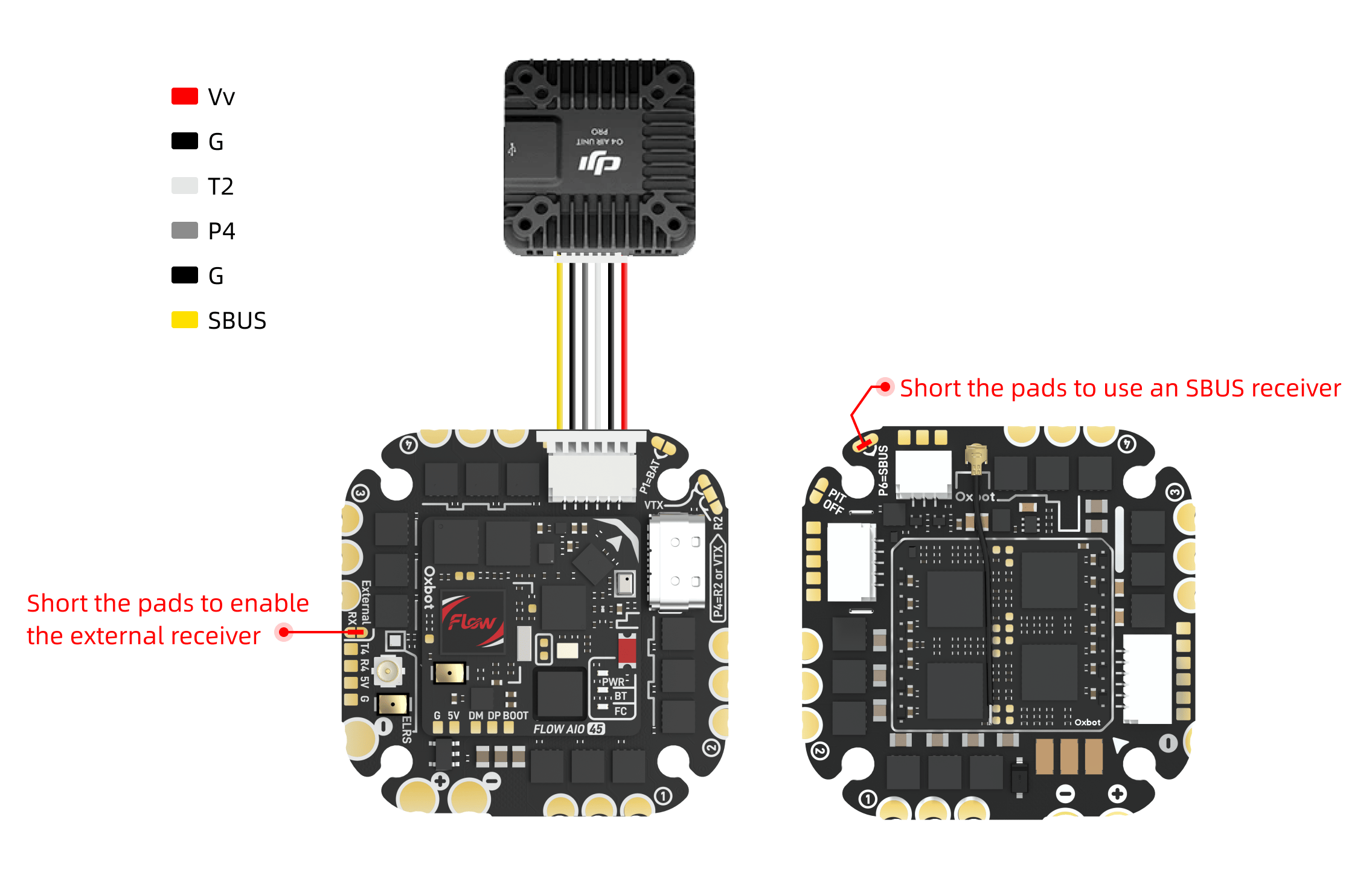
(1)非 SBUS 接收机:需要短接下图所示焊盘,以启用外置接收机。(1) Non-SBUS receiver: Short the pads shown below to enable external receiver.
(2)SBUS 接收机:需要同时短接"启用外置接收机"焊盘和"启用 SBUS"焊盘。(2) SBUS receiver: Short both "Enable External RX" and "Enable SBUS" pads.
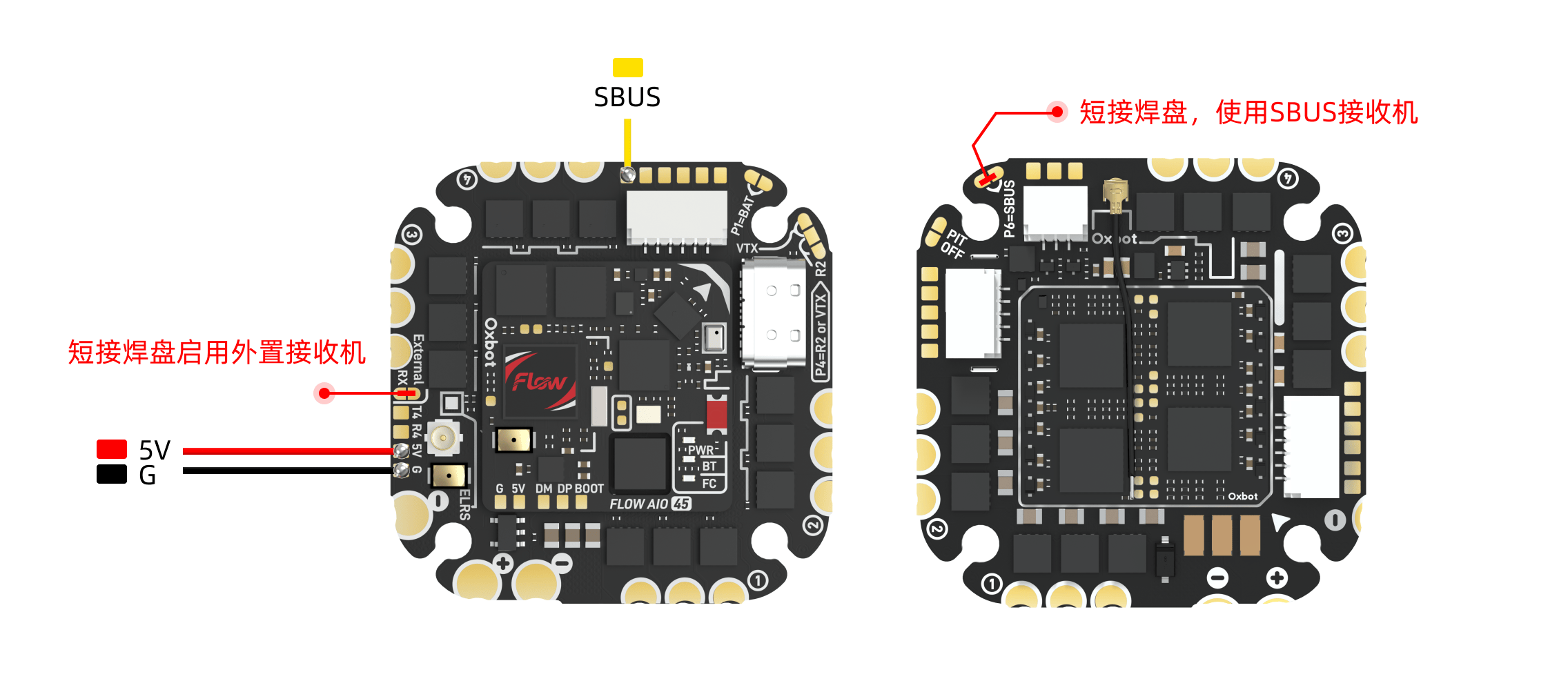
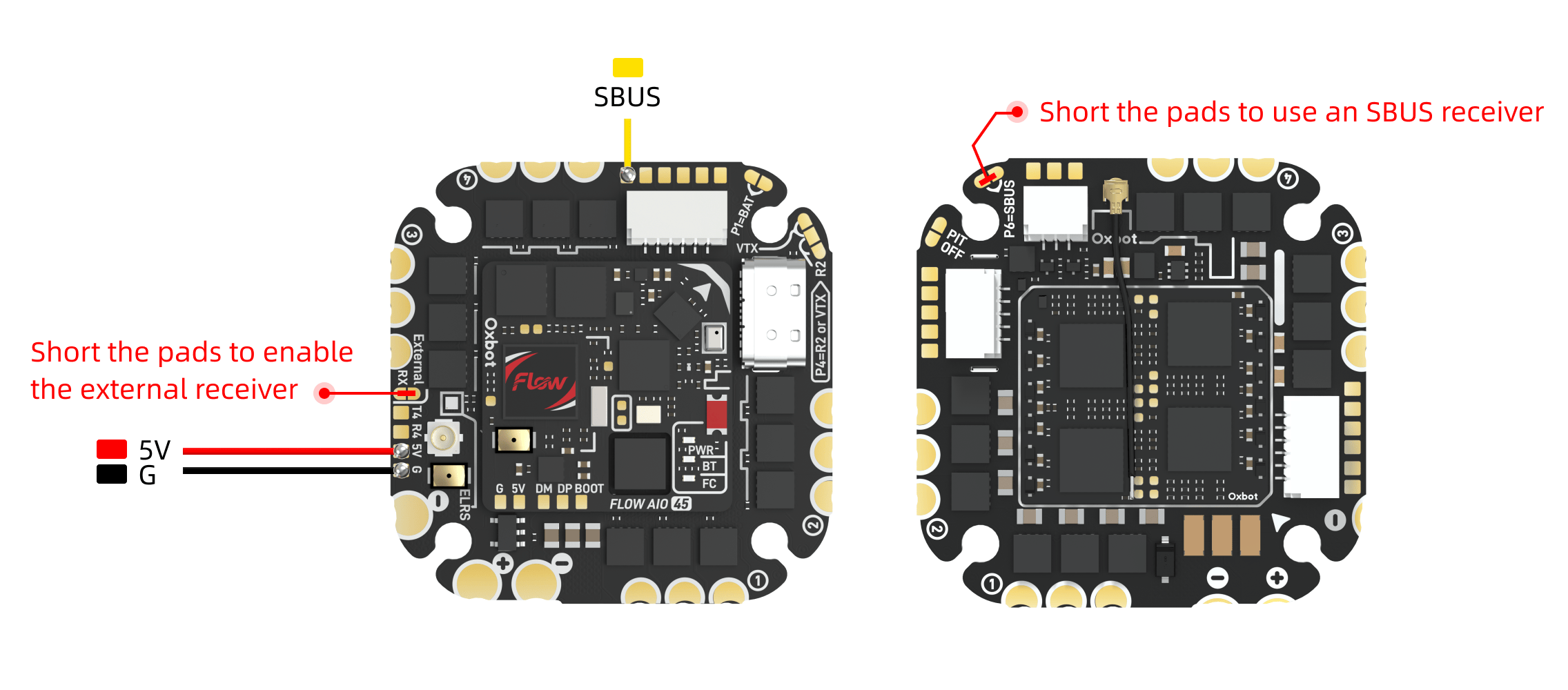
SBUS 接收机的信号线需要连接到图传排线座旁边的 SBUS 焊盘上(UART4)。若使用Dji天空端内置接收机,同样需要短接"启用外置接收机"焊盘和"启用 SBUS"焊盘。SBUS signal wire connects to the SBUS pad near the VTX connector (UART4). If using DJI air unit built-in receiver, also short both "Enable External RX" and "Enable SBUS" pads.
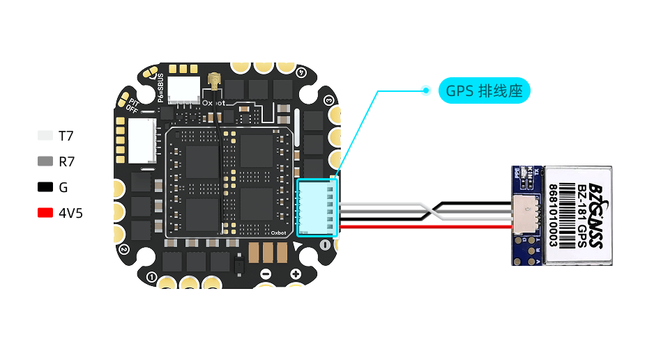
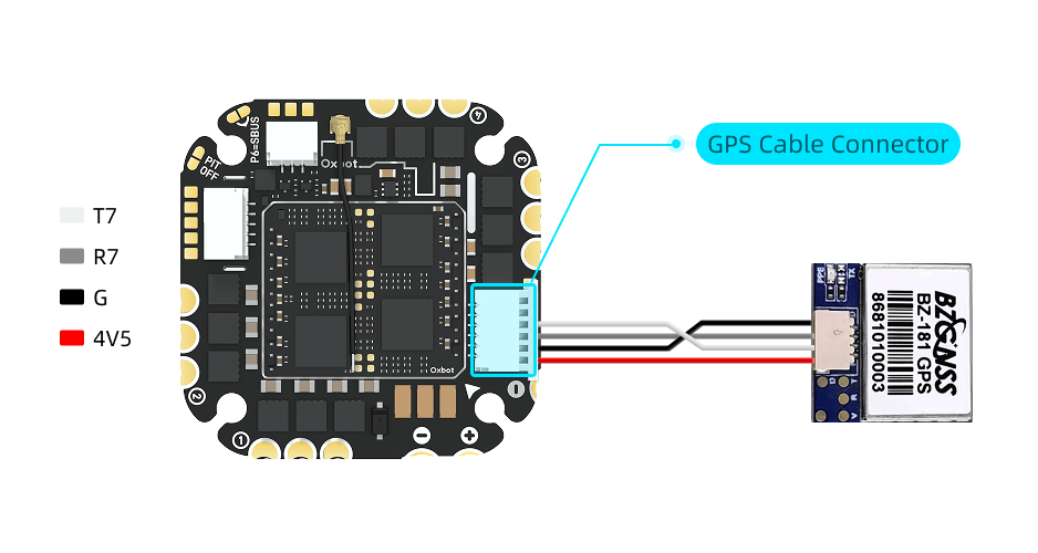
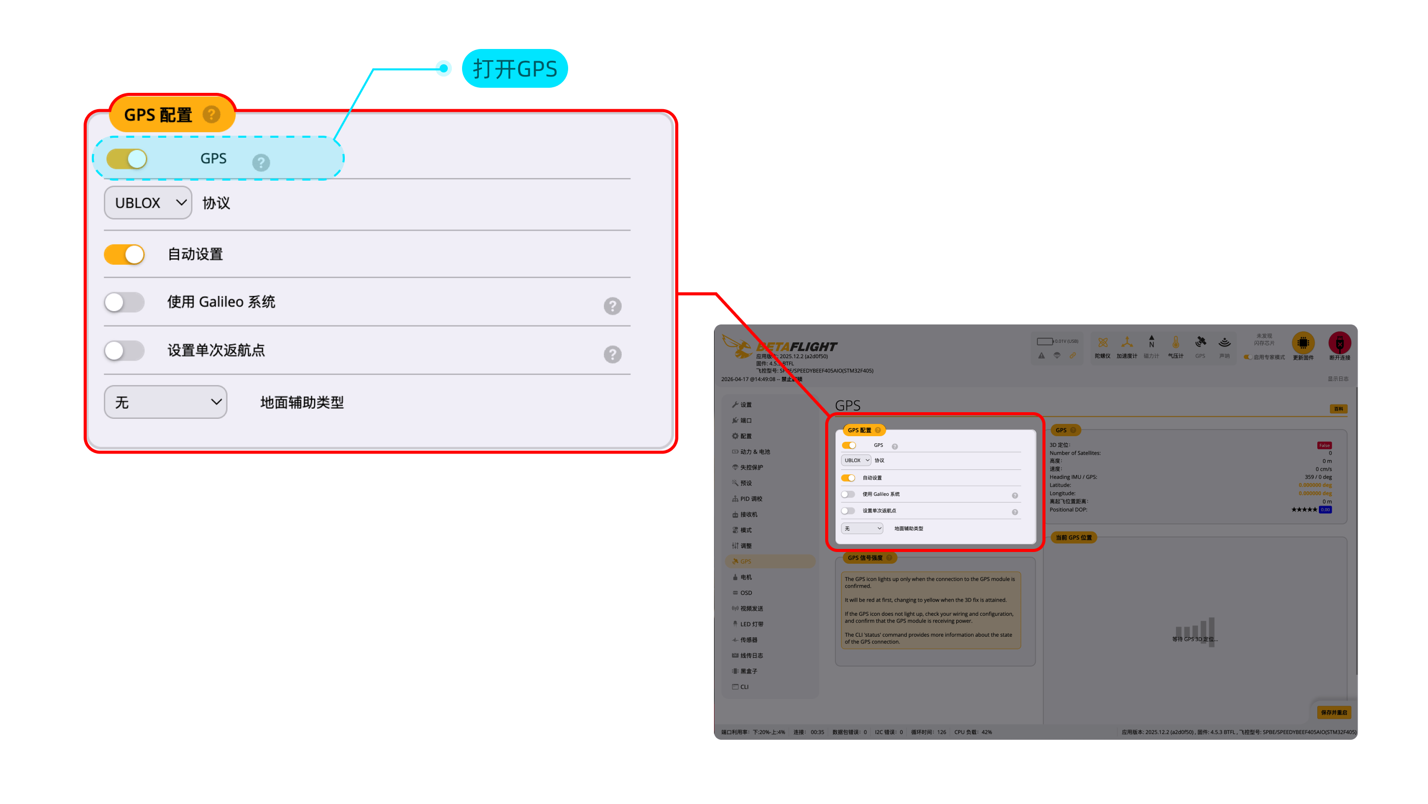
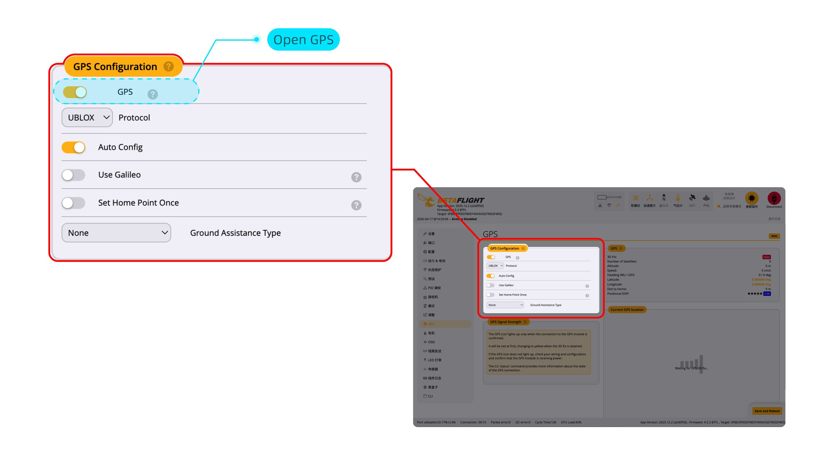
3.7GPS 连接GPS Connection
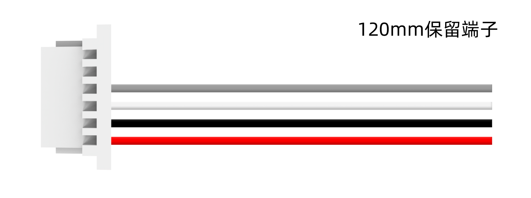
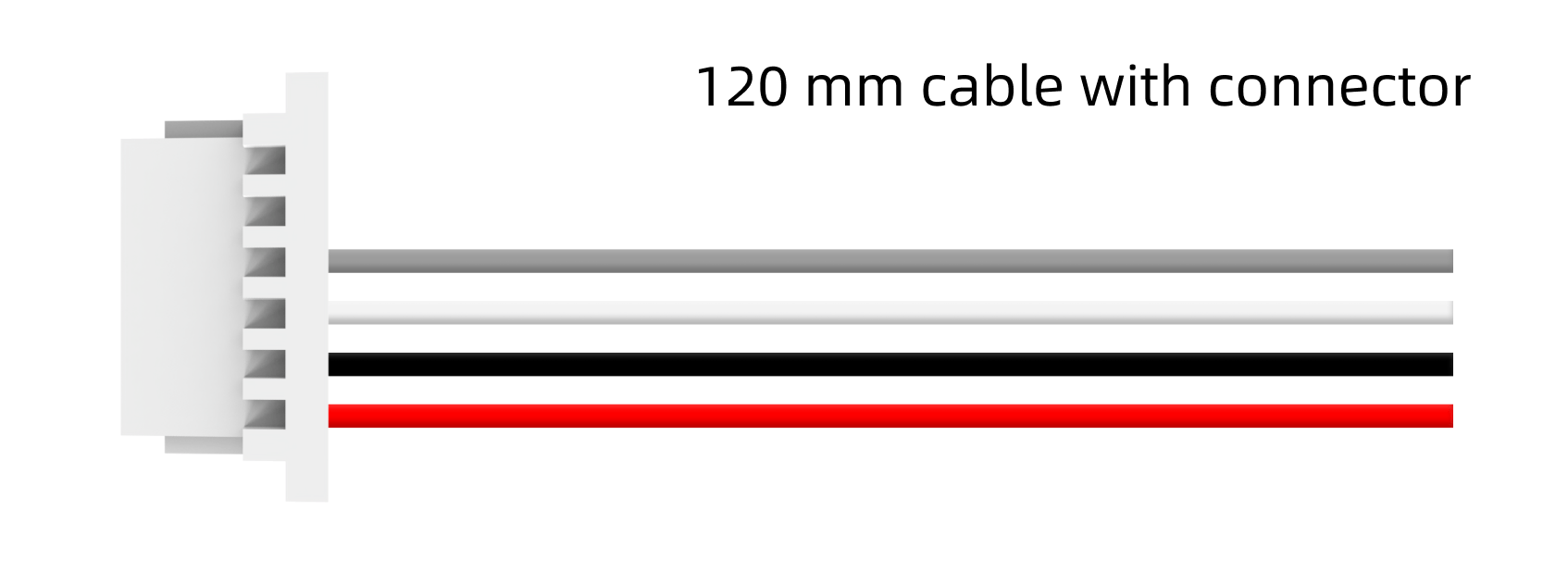
GPS 可使用配件编号 #26 的 GPS 120mm 4PIN 线材(见 1.2 包装配件概览)进行连接。该线材仅预装一端胶壳,另一端胶壳请根据 GPS 实际线序手动装配。Connect GPS using accessory #26 (GPS 120mm 4PIN cable, see 1.2). One end is pre-terminated; manually wire the other end per your GPS pinout.
下图以 BZ181 为例。Example below using BZ181.
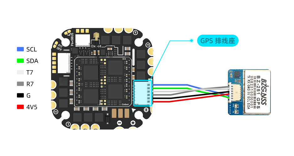
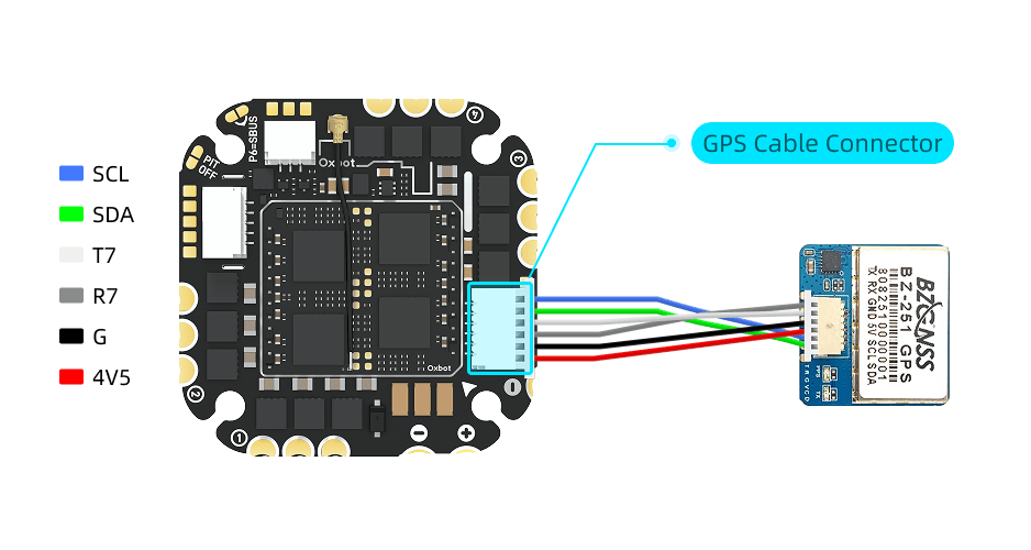
若 GPS 模块带有罗盘,可使用配件编号 #26 的 GPS 120mm 双头端子线连接 SDA 与 SCL;下图以 BZ251 为例。If GPS module has compass, use accessory #26 cable to connect SDA and SCL; example below using BZ251.
GPS 连接至飞控的 UART7 端口,出厂默认已完成端口设置。只需要在 GPS 选项卡中,打开 GPS 即可使用。GPS connects to UART7. Port settings are pre-configured. Just enable GPS in the GPS tab.
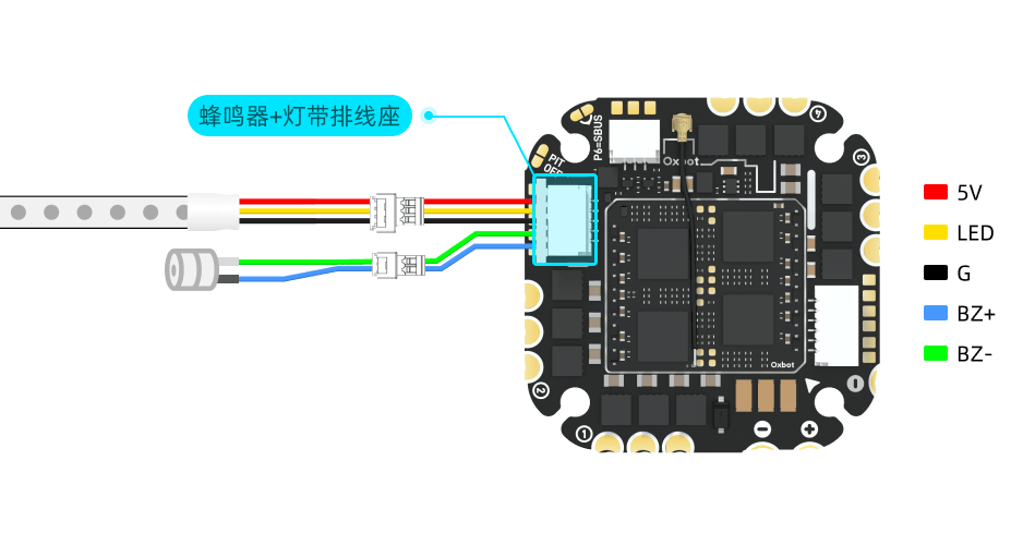
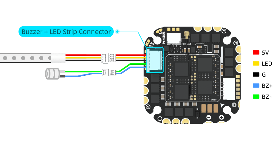
3.8LED 灯带 & 蜂鸣器连接LED Strip & Buzzer Connection
LED 灯带和蜂鸣器可使用以下配件进行连接:LED strip and buzzer can be connected using these accessories:
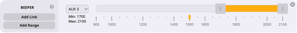
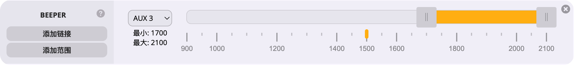
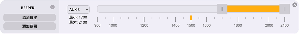
(1)蜂鸣器设置:蜂鸣器功能默认已启用,完成对应模式配置后即可使用。(1) Buzzer: Enabled by default. Configure modes as needed.

(2)LED 灯带设置:LED 灯带支持 Betaflight 控制模式和蓝牙控制模式两种工作方式。具体设置方法请参见 5.3"蓝牙灯带"。(2) LED Strip: Supports Betaflight control mode and Bluetooth control mode. See section 5.3 "Bluetooth LED Strip" for setup details.
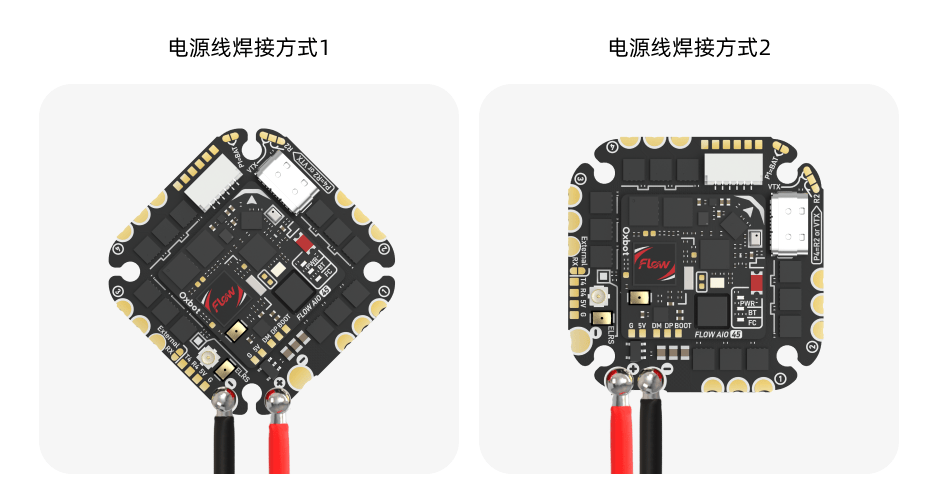
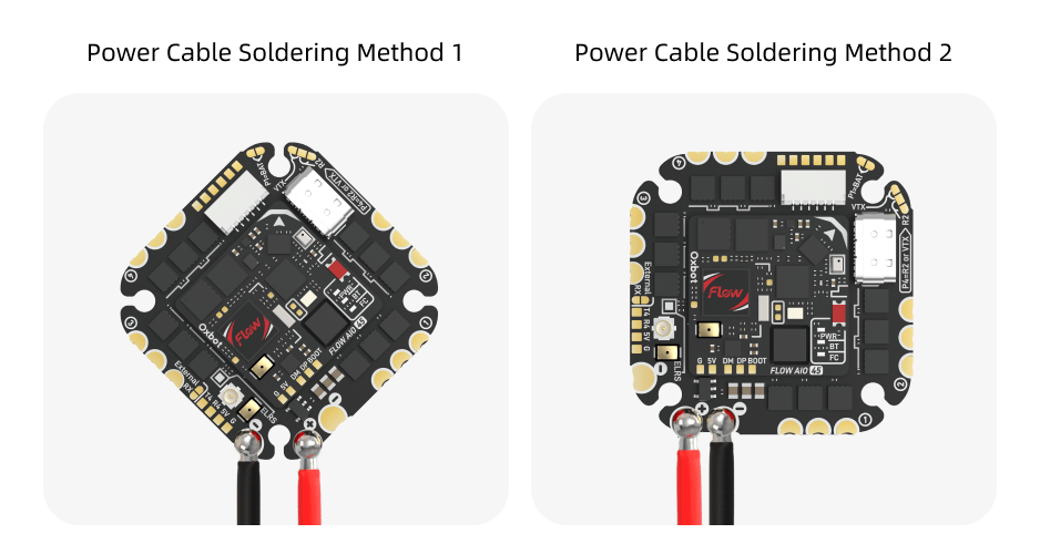
4.1电机与电源线连接Motor & Power Connection
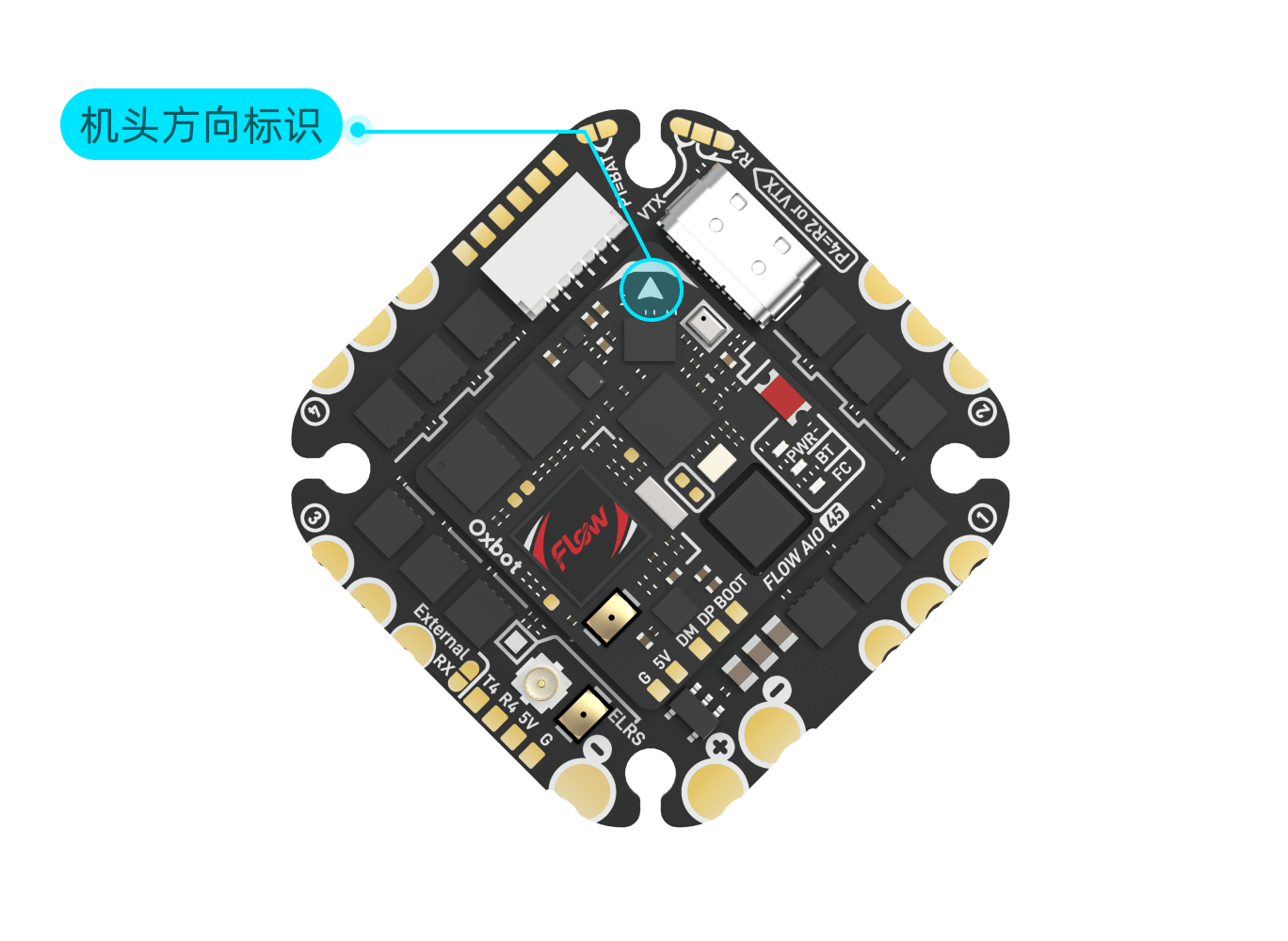
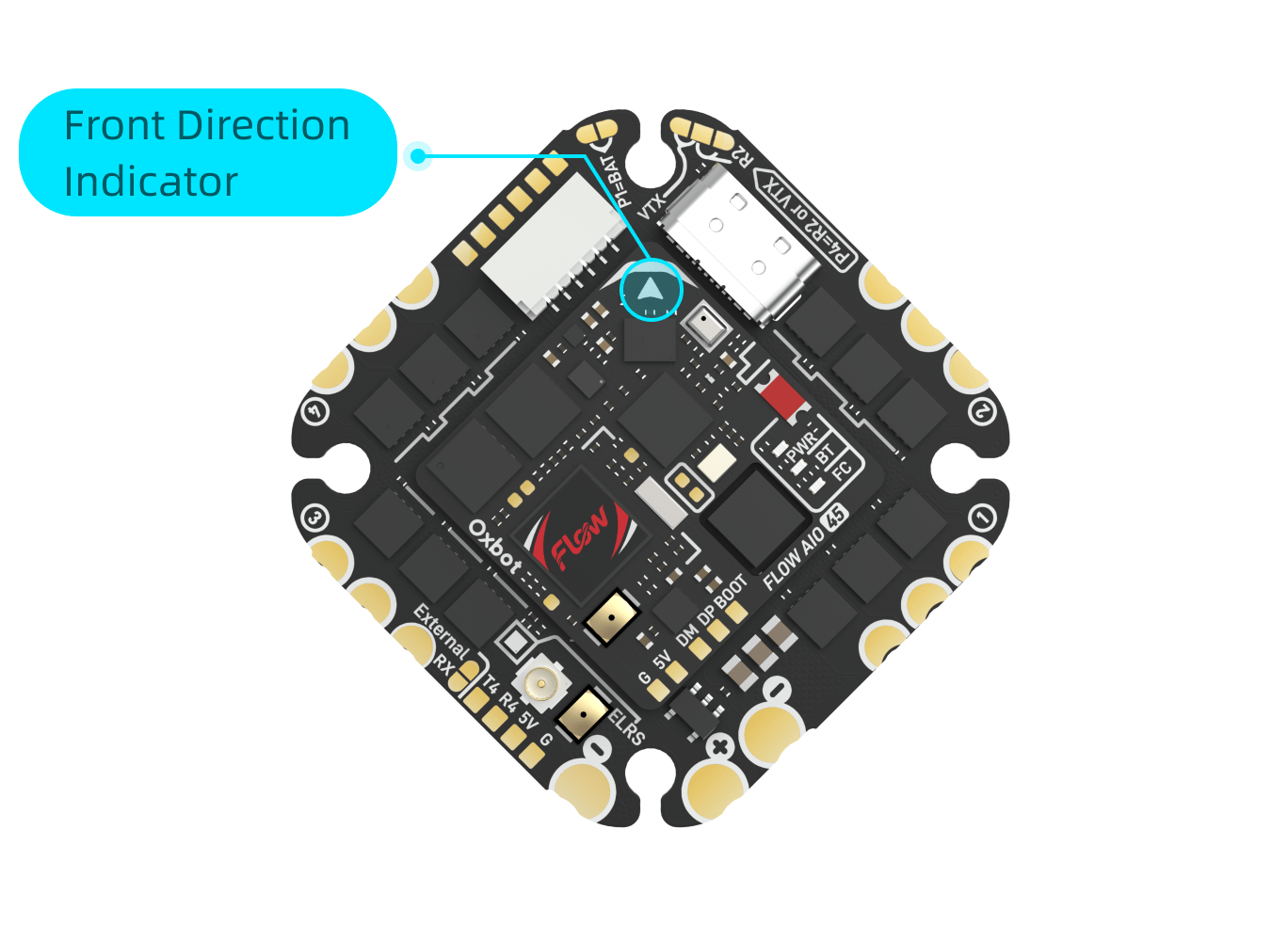
4.2飞控方向设置Orientation Setup
飞控默认按 45° 倾斜方向安装,安装时请参考飞控上的"机头方向箭头"。按默认方向安装时,无需更改设置。FC installs at 45° by default. Follow the "nose direction arrow" on the FC. No settings change needed for default orientation.
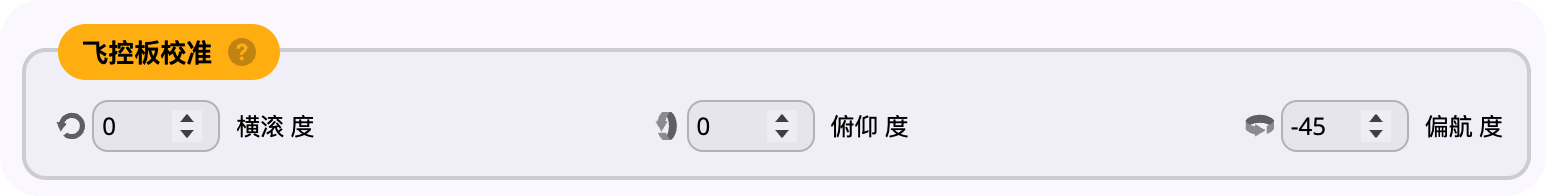
如需按下图方式旋转 45° 安装:If installing rotated 45° as shown below:
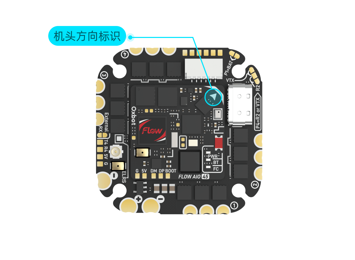
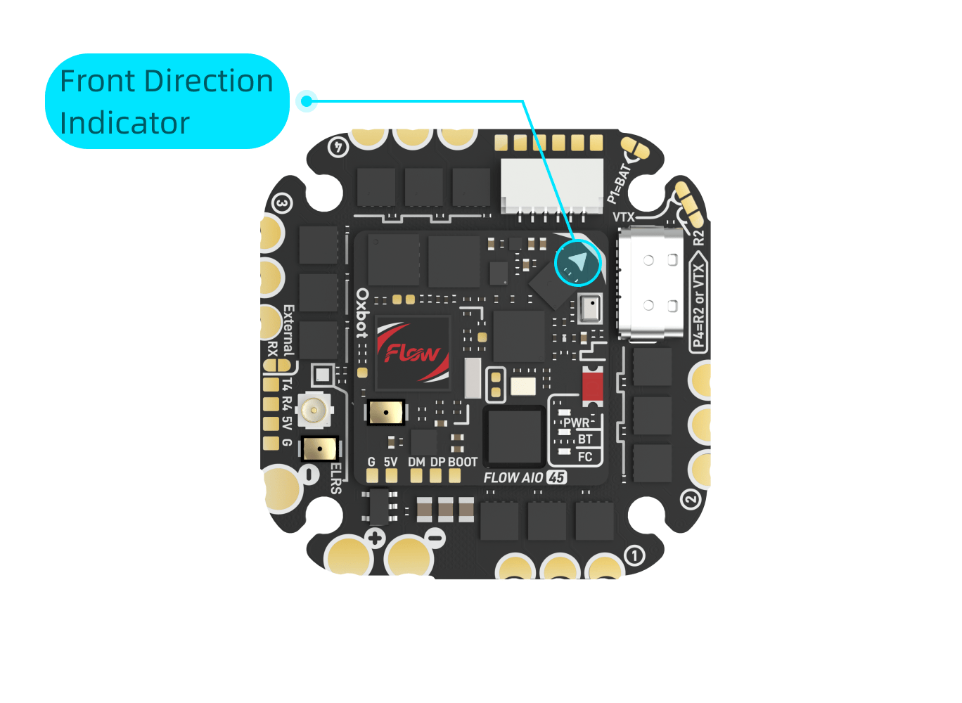
需要将偏航角度设置为 45°。Set yaw offset to 45°.

4.3转接板安装说明Adapter Board Installation
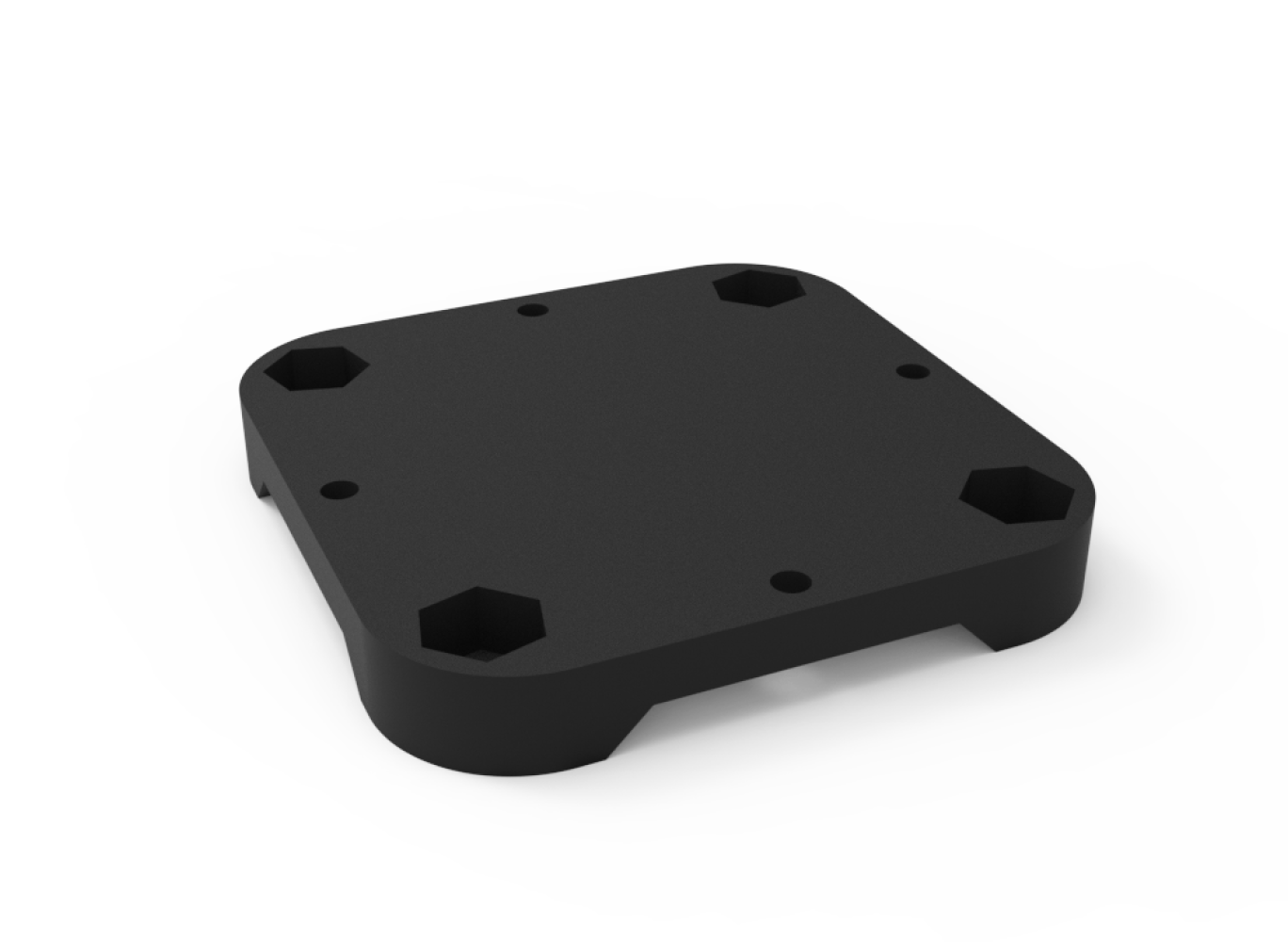
本产品附带配件编号 #8 的 30mm M3 转 25.5mm M2 转接板,可用于适配 30 × 30 mm (M3) 孔距的机架。安装步骤如下:Included accessory #8: 30mm M3 to 25.5mm M2 adapter board for 30 × 30 mm (M3) frames. Installation steps:

本产品随附 #3 1000μF 35V 电容、#4 470μF 35V 电容、#5 2200μF 25V 电容,可在 1.2 包装配件概览中查看。Included capacitors: #3 1000μF 35V, #4 470μF 35V, #5 2200μF 25V. See 1.2 for details.
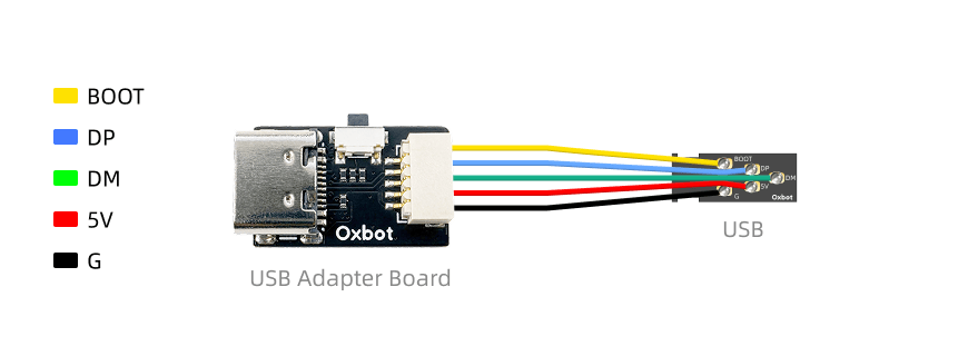
4.4USB 转接板安装说明USB Adapter Board Installation
USB 母座可以粘贴到机架上,用于将飞控 USB 口延长到机架外。USB 公头延长线用于插入飞控的 USB 口,另外一端没有插胶壳,可以连接配件的胶壳,连接到机架或是 USB 母座上。USB female socket can be attached to the frame to extend the FC USB port externally. The USB male extension cable plugs into the FC USB port; the other end requires manual shell insertion to connect to the frame or USB socket.

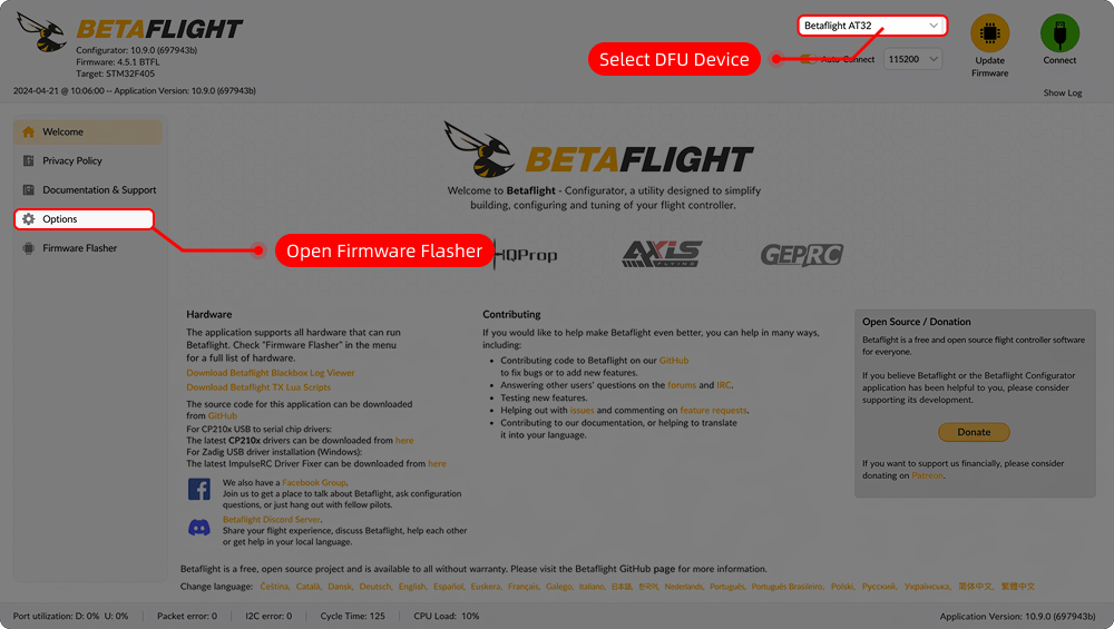
5.1连接 Betaflight5.1 Connect Betaflight
飞控出厂固件版本为 12.1。请使用网页版 Betaflight 地面站进行连接:Factory firmware version is 12.1. Use web-based Betaflight configurator:
5.2APP 连接5.2 APP Connection
FLOW AIO 支持通过 SpeedyBee App 进行蓝牙连接和参数调整。FLOW AIO supports Bluetooth connection and parameter tuning via SpeedyBee App.
App 下载链接:https://www.speedybee.cn/download.html App download: https://www.speedybee.com/download/
5.3蓝牙灯带5.3 Bluetooth LED Strip
在 App 中点击"流星灯带设置",系统会提示先开启流星灯带功能。开启后即可进入灯带设置页面。如需切换回 Betaflight 控制模式,可点击右上角的"使用 BF 灯带"。In App, tap "Meteor LED Strip Settings". System will prompt to enable the feature first. Once enabled, enter LED strip settings. To switch back to Betaflight control mode, tap "Use BF LED Strip" in the top-right corner.
(1)通过按键切换(1) Via Button
(2)通过 LEDLOW 模式切换(2) Via LEDLOW Mode

5.4ELRS 接收机对频5.4 ELRS Receiver Binding
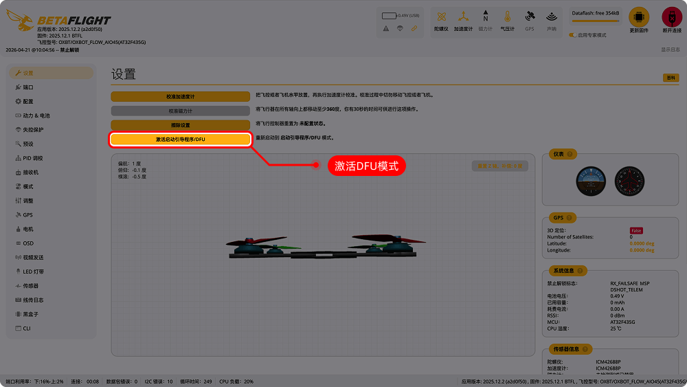
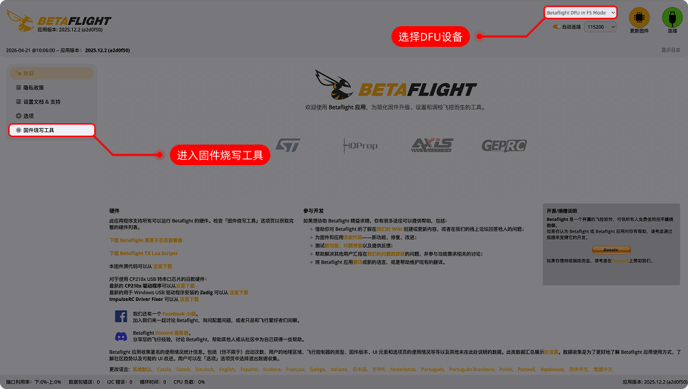
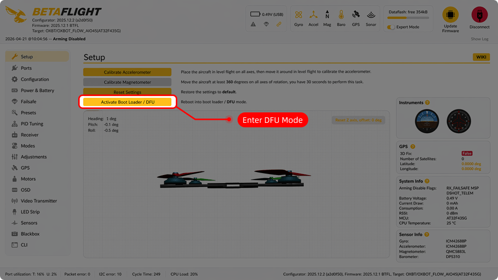
6.1主控固件升级FC Firmware Upgrade
6.2ELRS 接收机更新ELRS Receiver Update
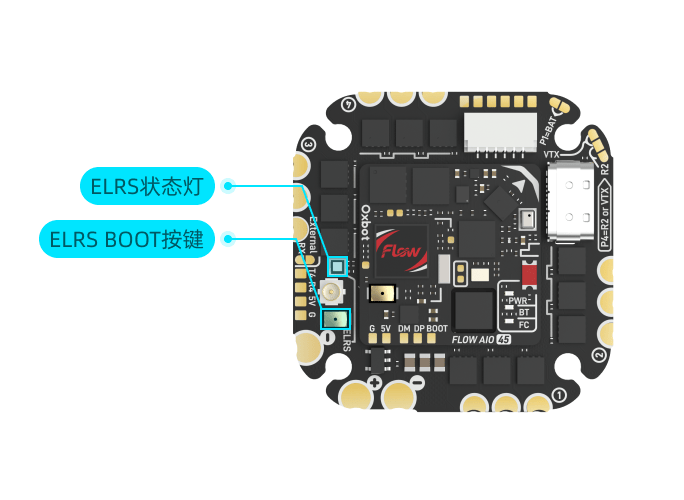
给飞控上电并等待 60 秒,期间不要连接遥控器。60 秒后,接收机状态灯变为快闪,表示已开启 Wi-Fi 并进入无线更新模式。Power FC and wait 60 seconds without connecting transmitter. RX LED will fast-flash indicating Wi-Fi mode is active.
(1)选择"Oxbot 2.4GHz RX"固件,点击"构建与烧写"。(1) Select "Oxbot 2.4GHz RX" firmware, click "Build & Flash".
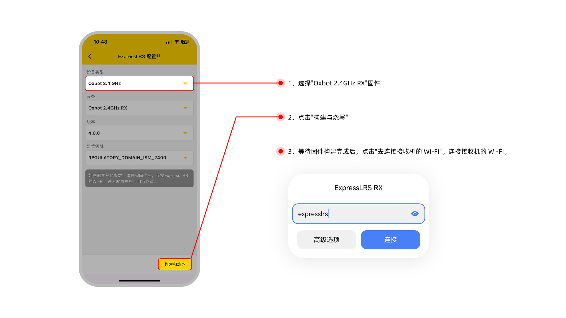
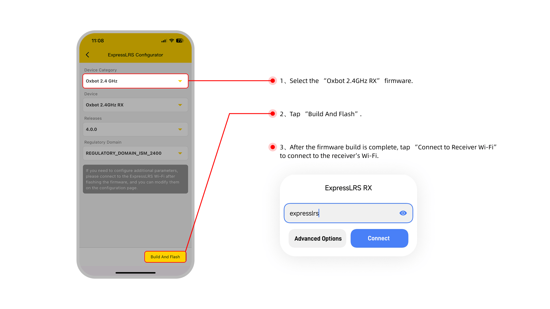
(2)直接连接接收机的 Wi-Fi:(2) Direct connect to Receiver Wi-Fi:
连接 Wi-Fi 后回到 APP。会自动刷写固件,等待进度条走满后,固件就更新完成。After connecting Wi-Fi, return to APP. Firmware will flash automatically. Update is complete when progress bar finishes.
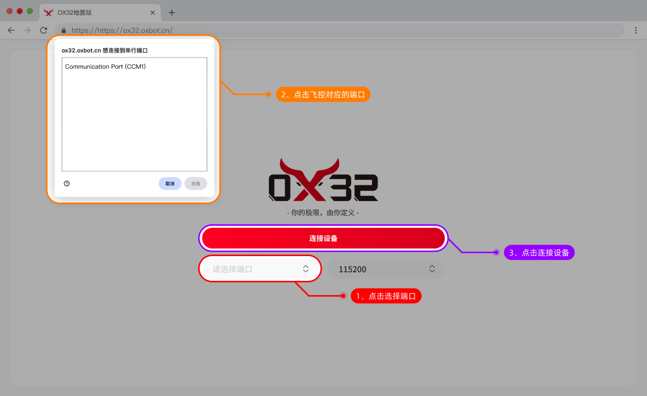
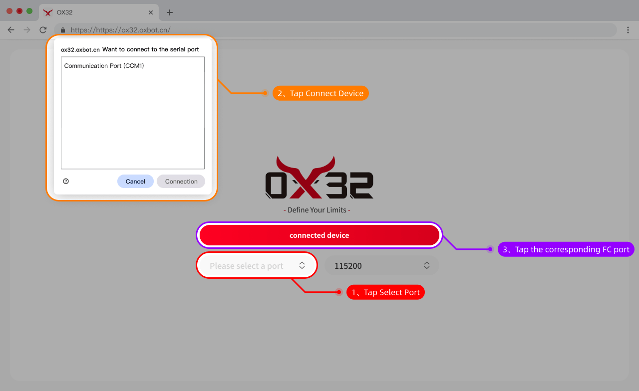
6.3电调地面站ESC Configurator
可以通过以下链接连接电调地面站:Connect to ESC configurator via:
https://ox32.oxbot.cn/ https://ox32.oxbot.com/
| 参数项Item | 规格Value |
|---|---|
| 产品名称Product Name | OXBOT FLOW AIO45 |
| 主控芯片MCU | AT32F435 |
| 固件 TargetTarget | OXBOT FLOW AIO45 |
| 陀螺仪 / 传感器Gyro / Sensor | ICM-42688P |
| 气压计Barometer | 内置Built-in |
| 模拟 OSDAnalog OSD | 支持Supported |
| 内置接收机Built-in Receiver | ELRS 2.4G 固件:Oxbot 2.4GHz RXFirmware: Oxbot 2.4GHz RX |
| USB 接口类型USB Port | Type-C,支持双 Type-C 接口线供电Type-C, supports dual Type-C cable power |
| 蓝牙调参 / 无线更新Bluetooth Config / OTA | 支持Supported |
| BEC 输出BEC Output | 4V5 / 5V:共 4A 图传端口:2A4V5 / 5V: 4A total VTX Port: 2A |
| 串口资源UARTs | UART1: 飞控蓝牙FC Bluetooth UART2: 图传 (MSP / IRC Tramp / SmartAudio)VTX (MSP / IRC Tramp / SmartAudio) UART4: 内置 ELRS / 外置接收机Built-in ELRS / External RX UART7: GPS |
| 输入电压Input Voltage | 3–6S LiPo |
| 电调固件ESC Firmware | OX32 |
| 安装孔位Mounting | 25.5mm × 25.5mm M2,可通过转接板兼容 30 × 30mm M325.5mm × 25.5mm M2, adapter for 30×30mm M3 |
| 尺寸 / 重量Dimensions / Weight | 36mm × 36mm × 8.5mm / 12.6g |
| 持续电流Cont. Current | 45A / 180A |
| 峰值电流Peak Current | 50A / 200A 10S |
| 支持电调协议ESC Protocol | DSHOT 600 / 300 |
| 电流计Current Sensor | 支持 6S:比例 85 / 偏移 -30000 4S:比例 85 / 偏移 -21000 3S:比例 88 / 偏移 -14716Supported 6S: Scale 85 / Offset -30000 4S: Scale 85 / Offset -21000 3S: Scale 88 / Offset -14716 |